Hello everyone,
Apologies if it seems like I’m asking another question everyday but could someone help point out why the following servo motor control project is not working? I’m following a guide project from Arduino. The pressure sensor is displaying correctly however the motor does not seem to be powered at all. (The guide also had the motor connected directly to the board)
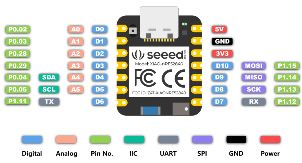
The servo motor is connected to the 5V, GND, and pin A1 (I believe this is capable of PWM). The analog sensor is connected to 3.3V, same GND and pin A0. The code is also attached below.
Thank you for your guidance!
#include <Servo.h>
#include <Wire.h>

Servo myServo;

int pressure;
int angle;

void setup() {
  // put your setup code here, to run once:
  myServo.attach(A1);

  Serial.begin(9600);
}

void loop() {
  // put your main code here, to run repeatedly:
  pressure = analogRead(A0);
  Serial.println(pressure);
  delay(50);

  angle = map(pressure, 0, 1023, 0, 179);

  myServo.write(angle);
  delay(50);

}
Hi there,
Not a bad question if you don’t know…
Post a picture how it’s connected the Xiao is a 3.3v device, so Not sure if your servo is looking for a 5v PWM signal or the lower 3.0 V PWM the xiao outputs. check that, Also can you print the Angle Int as well what are they reading?
Provide some serial output and lets look.
HTH
GL  PJ
PJ
also may want to try with GPIO pin “P0.03”

Where is the 5V?
Is the 5V sufficient to power the motor?
If the BSP is mbed, the following sketch got the motor running without problems. non-mbed BSP does not seem to support Servo.h.
#include <Servo.h>
#include <Wire.h>

Servo myServo;

int pressure;
int angle;

void setup() {
  myServo.attach(A1);
  Serial.begin(9600);
}

void loop() {
//  pressure = analogRead(A0);

  for(int i = 0; i < 1023; i = i +100) {
    pressure = i;
    Serial.print("pressure=" );
    Serial.print(pressure);
    delay(100);
    angle = map(pressure, 0, 1023, 0, 179);
    Serial.print("\tangle=");
    Serial.println(angle);

    myServo.write(angle);
    delay(500);
  }
}
Hey PJ,
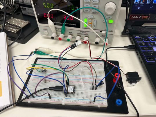
The connection is as per the image, I’ve added the power source to drive the motor. also connected a 100 uF capacitor. The motor I’m using is the SM-S2309S as such. I am not sure if the motor requires a 3.3V or a 5V PWM as a direct connection on an STM32 Nucelo board was able to drive the motor very efficiently.
Lastly, the angle has been printing out correctly. It just seems that the motor is not getting any power.
Thanks for any help PJ!
Hey msfujino,
The motor is connected to a 5V 1A power source like the previous reply!
Hey msfujino,
Thank you for the test code, my BSP is mbed as well. However, once again the motor is not moving or making any noises for that matter. Could this be a PWM issue? Any guidance would be greatly appreciated.
THank you!
You am creating “angle” from “pressure”, but are you getting “pressure” correctly?
My code is running without the value of puressure.
Yes, the pressure is printing correctly. I am also printing out the angle and that works too. Just seems like the motor is not working even though it worked fine on my STM32
Will it work with my code?
It looks like a slightly larger servo motor, but it requires a large current at the moment it starts moving. Is there any current limitation functioning in the power supply unit?
I tried your code as well and the motor still won’t move. The power supply unit have been limited to 1 A as I was following along to this guide.
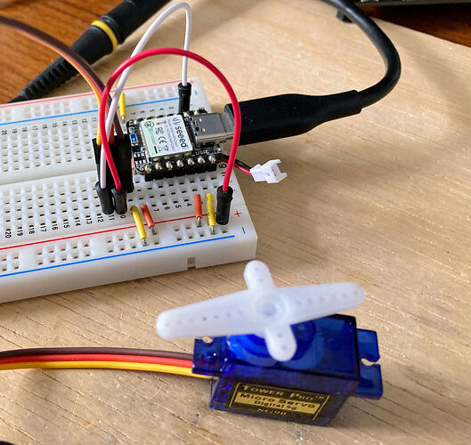
The one I am running in front of me right now is an SG-90. Probably not that different from your motor. The 5V power supply for the motor comes from the 5V pin of the XIAO.
Could you please show me your connections? If you don’t mind of course
Please zoom in to check. Works at 5V or 3.3V.
I am very confused, I just switched over to an SG90 like yours and made the same connection and then ran your code and its not running either
My environment.
//BSP : Seeed nRF52 mbed-enabled Borads 2.7.2
//Board : Seeed nRF52 mbed-enabled Borads / Seeed XIAO BLE Sense - nRF52840
The most likely cause is poor contact with the breadboard, jumper wires or connectors. Why don’t you try with as few connections as possible.
Are you sure about the soldering of the XIAO pins?
Thank you msfujino,
I apologize for wasting your time as improper soldering was the cause of the problem. However, thank you so much for taking your time to assisst me.
Good for you.
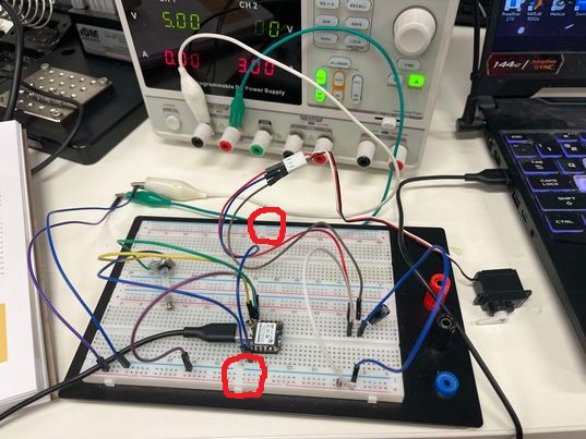
I was wondering about one point. Are the red circles on the breadboard connected?
They’re not normally but I think if you power the board with the red, black and blue connections on the right then they can share a power source


