Hello.
Please help me.
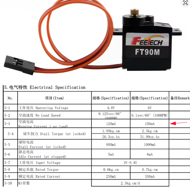
microcontroller Xiao nrf52840, servo feetech FT1109M connected to pin 5 and external power supply 5V 5A
a simple code:
#include <Servo.h>
Servo servo;
void setup() {
servo.attach(D1);
}
void loop() {
servo.write(100);
}
The servo rotates to the specified angle and shakes. If I connect the servo to the arduino nano, there is no shaking, everything works fine. Why does the servo shake when connected to the NRF52840 sense?
Hi there
And welcome here…
The Nano works because it outputs 5V PWM that the servo expects. The Xiao doesn’t. A logic level shifter or an external PWM driver (like PCA9685) will make it rock solid.
-
- nRF52840 GPIOs are 3.3V, while Arduino Nano uses 5V logic.
- The FT1109M servo is designed for 5V control signals. It may not reliably interpret the 3.3V PWM from the Xiao as a “clean” HIGH signal, especially under load.
- Grounding or Current Surge Issues
- Even with a 5V 5A supply, ground must be shared between the Xiao and the servo power supply.
- If not shared, the signal reference floats, leading to misinterpreted PWM edges.
- Also, servo motors create voltage dips/spikes; Xiao may not tolerate that as well as the more forgiving Arduino Nano.
HTH
GL  PJ
PJ 
Confirm that GND from the Xiao is tied to GND from the servo power supply. 
I have no issues driving the FeeTech (and similar) Servo modules with ESPs, NRFs and MG24s.
While the operating voltage is 4.6-6V the signal voltage is 3-8.4V
I would however recommend the use of the NRF library… eg
#include “NRF52_ISR_Servo.h”
Hello!
An error occurs during compilation
"
WARNING: library NRF52_ISR_Servo claims to run on nordicnrf52, nrf52 architecture(s) and may be incompatible with your current board which runs on mbed architecture(s)."
Hello!
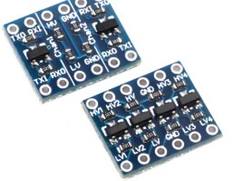
I used a 3.3-5 logic level converter, but unfortunately it didn’t solve my problem. Please help me figure out what’s the matter?
Hi there,
Sure, Can you post a picture so we can look?
are the GND’s tied together?
@grobasoz has some practical recent experience with them so maybe he will see something too.
Your not the first one to run into it, so hang in there
you have a couple areas to check and it will work.
HTH
GL PJ
For clarity, I recorded a video.
I’ve been trying to solve this problem for a long time. I’ve used different servo machines, different power sources, soldered everything together, and even bought a different xiao, but I still can’t get rid of the shaking.
I really want to use the Xiao NRF52840 sense, as it has everything you need in a miniature case.
I wasn’t using mbed on my devices here. I can try later.
I agree… sounds like power brownout to me… IMO
Probably not… 150mA required, 1A max?
Could you show us a simple illustration that clearly shows the part names and connections?
it looks like to me you have too much going on… what does the mosfet do? … in any event the sound is the servo hunting for zero point… you should revise the sketch to sweep and it will have no further problems
Hello!
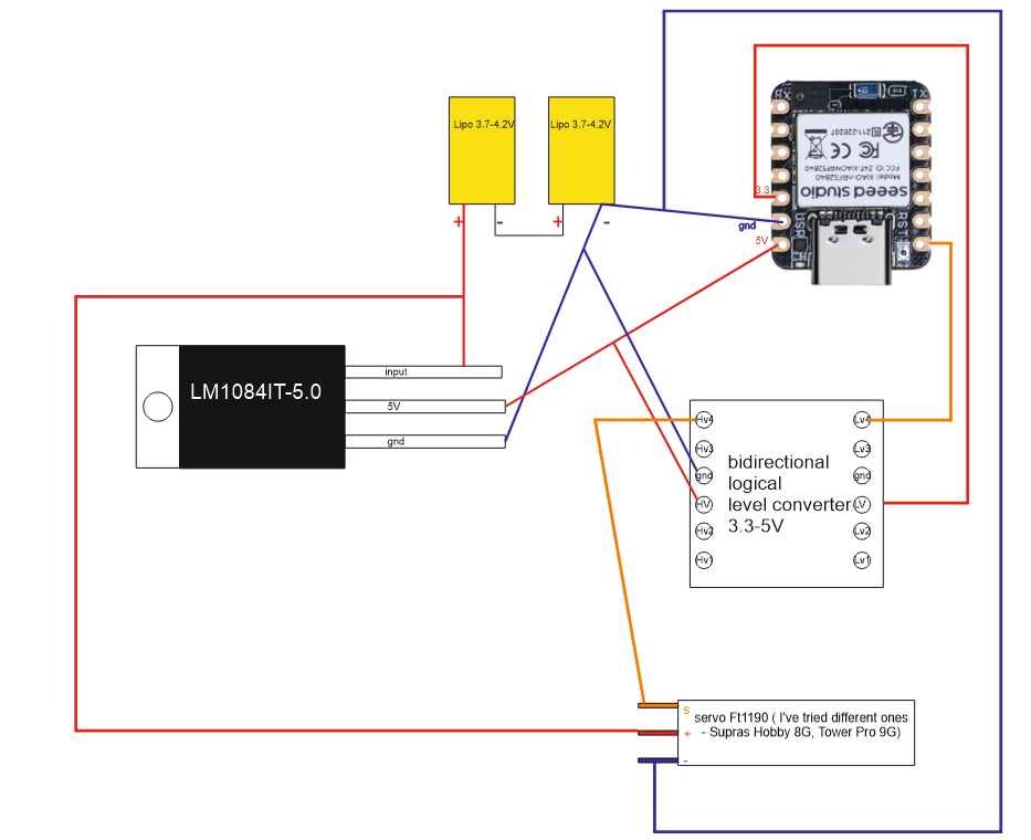
I tried to connect it in different ways. I put electrolytic 470mkf and ceramic 100nf capacitors to power the microcontroller. I put Schottky diodes on the “+” servo, and on the power supply of the controller. I bought a new xiao, I bought new servos. Everything is always spinning and working, but the servo is always shaking too. The diagram in the video above is like in this picture.
Hi there,
So at first Glance… Why is the 3.3 v connected through the logic converter with the output connected to 5V EDIT, It’s bi_directional so dis reguard this comment(NO-NO)  “remove the wire on the output tied in with the 5V connection from the E-regulator” NOW!.
do that First but switch Pins to D2 and here is why.
the Xiao nRF52840 has limitations compared to typical ESP32 or Arduino boards when it comes to servo PWM.
 Key Notes First:
- The nRF52840 does not have dedicated hardware PWM for every GPIO.
- It uses a PWM peripheral (4 instances on the chip), each with 4 channels, mapped via PPI and GPIOTE.
- For best results with servos, you want:
- A dedicated PWM instance (not shared),
- A GPIO that’s not also used for debugging or SWD, and
- Avoid pins that have quirks (like P0.00 or P0.01, which are NFC by default).
 Best Pin Candidates for Servo on Xiao nRF52840:
| Label |
Pin Name |
Notes |
| D2 |
P0.02 |
Excellent choice: standard GPIO, no SWD/NFC conflict |
| D3 |
P0.03 |
Also solid; commonly used for PWM |
| D6 |
P0.31 |
Often used for analogRead (VBAT), but available for PWM if unused (Not anymore) |
| D9 |
P0.13 |
Safe choice if D2/D3 are busy |
 Avoid Using:
- P0.00 / P0.01 (D8/D9) if NFC is not disabled (they’re NFC by default).
- SWD Pins (D7 = P0.18, D8 = P0.20) unless you’re not debugging or you’ve reassigned them.
Because hardware PWM on nRF52840 can be tricky across pins, sometimes it’s easier to:
- Use
SoftwareServo or Adafruit_TinyServo,
- Or map one PWM channel to your servo pin of choice using Nordic’s
nrf52-pwm approach in Arduino
then try this:
#include <Servo.h>

Servo myServo;

void setup() {
  myServo.attach(2); // GPIO D2 = P0.02
  myServo.write(90); // Center position
}

void loop() {
  // nothing for now
}
are those level shifters or are they RS-232 to TTL ? I see in the picture TXD & RXD ? double check they are tru level shifters.
I would switch pins though you have the servo command on D0 a known strapping pin on the Xiao not so sure that’s good idea. my .02
HTH
GL  PJ
PJ 
regulated 5v (center pin) should connect directly to the servo power… i think you could probably do away with the level shift all together… IMO
Konstantin,
The connection seems to work fine.
Can you give us a link to the specifications of the level converter used? If a slow level converter for I2C is used, the signal may be attenuated and not propagated.
It may work without a level converter.
Please measure the INPUT and OUTPUT voltages at the LM1084 terminals and let us know.
Is the battery fully charged?
The operating voltage of the FT1190 is 6V or less, so please supply 5V to the + pin.
Hi there,
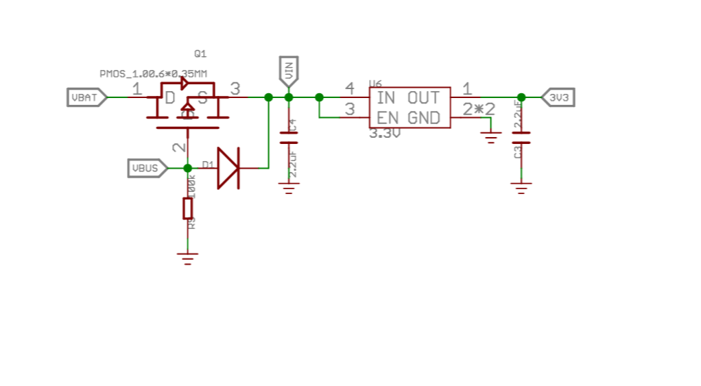
So I don’t like the schematic you show,
How can you connect 3.3V INTO the Xiao when it’s an OUTPUT?
here is the chunk from the schematic
I think hook the Servo to 5V only too… disconnect the 3.3v wire and just use the USB to power the Xiao and be sure the grounds are connected.
it will work I think. I have some stuff I’ll have to set something up, be sure batteries are fully charged.
HTH
GL PJ
Hi PJ,
Judging from the video posted by OP, the level converter used is probably a slow level shifter for I2C consisting of FETs and pull-up resistors. The wiring from the XIAO’s 3V3 pin to the level converter is probably to supply 3.3V to the 10k pull-up resistor on the board.
I’m not sure whether the servo OP is using is for a single cell or a dual cell, but if it’s for a single cell, the voltage may be too high in a series battery, causing excessive servo gain and vibration.
Hi there,
Ah’ Ok, makes better reason then, I never like to use the 3.3v to put into power , just as an output per the spec’s to power a temp sensor or something less than 140ma.
Your probably right about the speed to , it’s hitting the end of capable…
Good stuff though
GL PJ
I’m not cool on the specs to the servo…so ??