Hello @wx4cb and @ansonhe97…
I did some more experimentation today and tested some working UART code to see if I can read input from the D0 pin of the 28-pin header. In short, I can’t.
This image is taken from my logic analyzer with the probe at on the Tx pin of the Adafruit Ultimate GPS I have used on several projects in the past. You can see in the screen shot the start of the string “$GPRMC,” which is one of the normal GPS data strings. There were many other normal output strings seen as well–in fact the logic analyzer didn’t seem to detect any framing errors from the GPS when read directly.
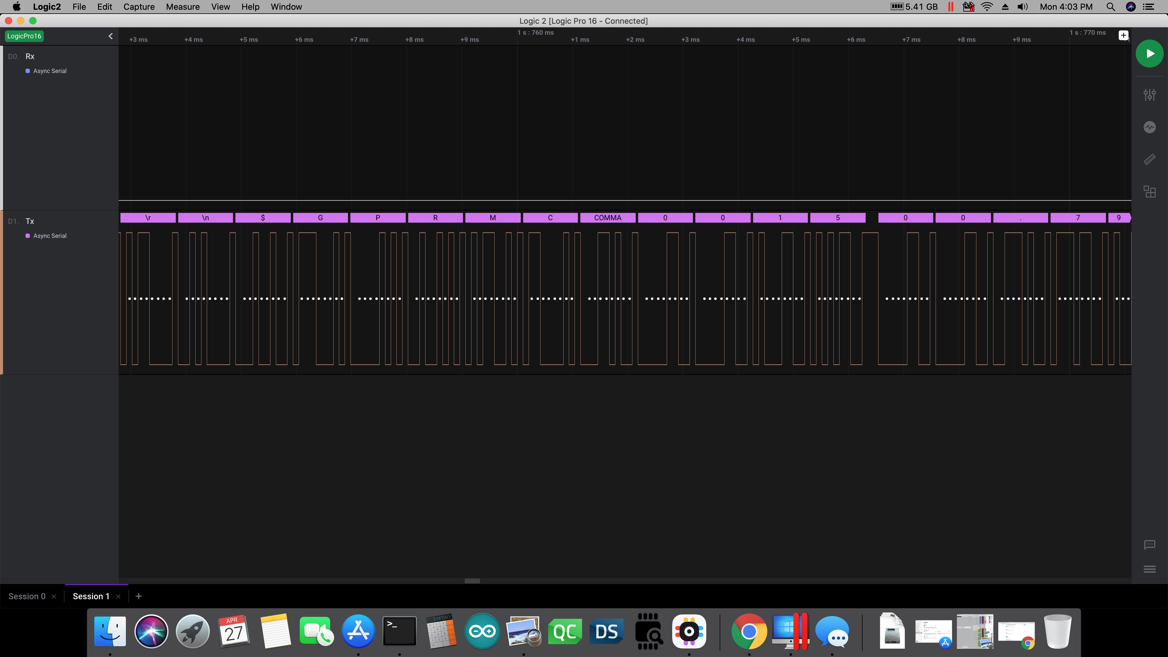
As you can see, there is ASCII data on the Tx pin from the GPS. There was nothing on the Rx pin going to the GPS however, which is exactly the behavior I was expecting to see–as I had the logic analyzer right at the GPS unit. Note that in this image the other LA probe was removed from the Rx pin, which is why that level is LOW; but I did the test many times with both probes attached to the respective pins on the GPS, and got exactly the behavior I was supposed to see. Since I have used this GPS with this code (see below) many times before, I know it all works.
Here is the code that was running on the SAMD21 chip when I grabbed that screen shot:
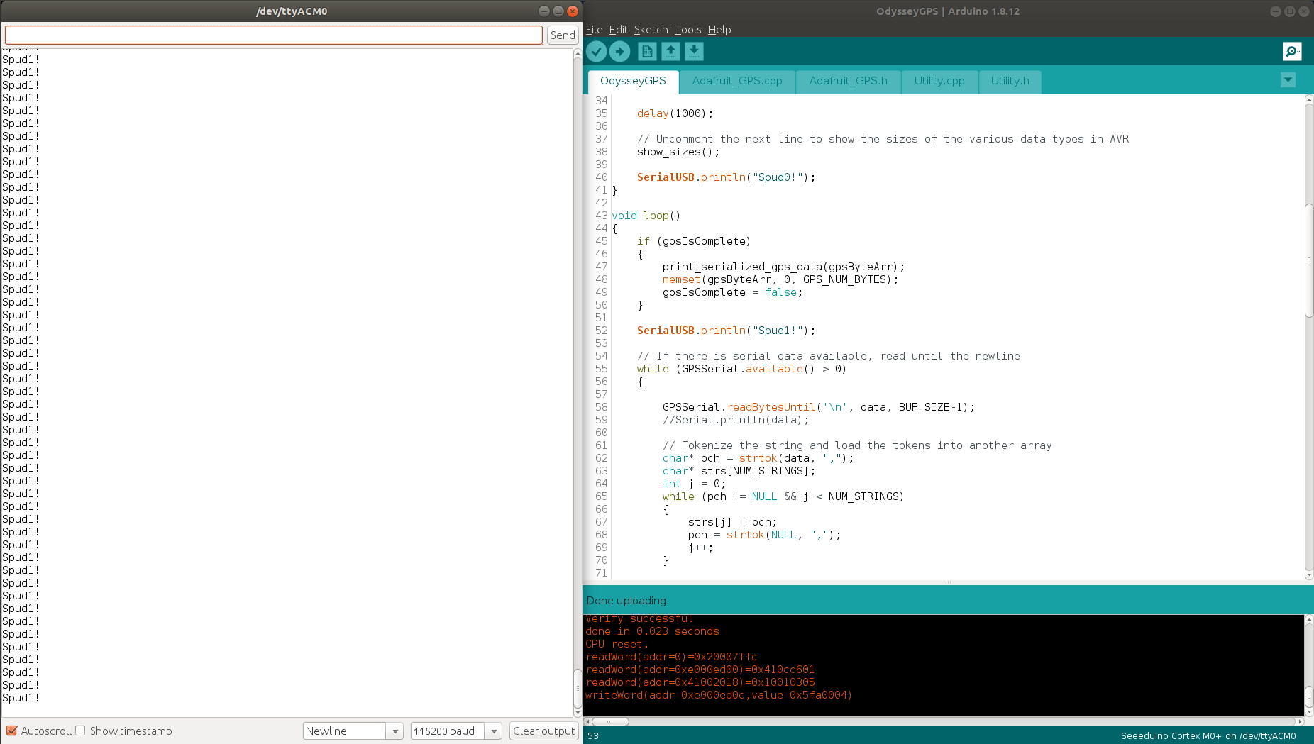
The thing to notice in that image, is the code at line 52–it’s printing that line of output to the SerialUSB output, but then it’s never entering the while loop at line 55. I did have that “Spud1” print call inside the while loop, but moved it back out because it was never getting printed…because the while loop was never getting entered. But the code works with the Teensy I was using right before this–I only had to change all the Serial calls to SerialUSB to run on the Odyssey board. That’s really the only change I had to make. So for whatever reason the call to GPSSerial.available() is returning either a zero or a negative number. It’s certainly NOT returning a positive integer which it should be–especially given the output you see in the previous image.
There are a few other thoughts I had today…
-
Regarding the 4-pin header. This cannot have anything to do with the Arduino’s output of course, because if you need to reset the SAMD chip, you have to momentarily jumper the Tx and Rx pins on that header. So if you have them both attached to some serial device, the chip will be getting reset constantly–and in fact it’s not even available in the Arduino IDE. It just isn’t listed. So other than to reset the SAMD21 chip, it obviously has no other purpose…at least from the perspective of the Arduino user.
-
I uploaded the code from a blank sketch onto the SAMD21 chip today, and re-applied the logic analyzer to the Tx/Rx pins on the 4-pin header. The LA showed the exact same waveform as I saw before (posted in my previous reply above). In other words, the Tx pin shows a semi-symmetric square wave with about 10 ms of ON time, and about 6 ms of OFF time. The Rx pin is always LOW when the Tx pin shows this pattern. The point here is that whatever is going on in the x86 board (BIOS, possibly?), it’s sending that square wave out the Tx pin on that 4-pin header.
-
Overall, I think there is something really screwed up with the serial port functionality on this SAMD21 chip. Not only do I get the behavior I’ve been describing and showing in the screen shots, but another concerning issue I am seeing is that if you try to send a character out the SerialUSB’s Tx pin, nothing happens…until the IDE locks up after the 3rd or 4th attempt. So you then have to force kill the IDE and restart it, and much of the time you have to actually jumper the Tx/Rx pins on the 4-pin header in order to get the SAMD21 chip to respond to programming again. I’ve tried with three different versions of the Arduino IDE (two on Windows, one now in Linux), and get the exact same behavior–pointing to an issue with the board. (Can you confirm this behavior @wx4cb?)
-
Finally, I still can’t explain all the framing errors I have been seeing on Serial1 when I send data from that. In short, the output seen on the SAMD21 Tx line (pin D1) has virtually no uncorrupted data–there are framing errors pretty much everywhere.
So I would like to request that @ansonhe97 address this serial issue, and also provide us with more documentation as to how they’ve implemented this SAMD21 chip in the hardware. I did download the Atmel-SAMD21 datasheet from the link at the bottom of the Getting Started page for the Odyssey board, but haven’t really gone through it yet. I will start looking through it tonight though.
But as far as I can tell, there is most definitely something wrong with the implementation of the Serial1 port on this x86 Odyssey board.
TB