i want to use the serial port on the PI header, what are the linux device names for the port on the pi header ?
ok so apparently it’s /dev/ttyS4, but what are ttyS5/6/7 ?
also… what are the rx/tx pins tied to that are next to the 28 pin header? they don’t seem to be tied to ANY serial port either any of the arduino pins or any of the linux serial device names - outlined in red dotted line
Hi,
The ttyS5/6/7 serial ports are used internally, and they did not lead out on the hardware.
For the Rx/Tx on the 4 Pin, this is connected to the SAMD21, which means two hard serials can be used on SAMD21 of Odyssey X86.
ok so the D0/D1 pins are different to the RX/TX pins on the 4 pin header?
If so, what are they referred to as in the arduino IDE?
@ansonhe97: to which UART device are these Tx/Rx lines on the 4-pin header mapped? I tried using a logic analyzer to evaluate them yesterday, and all I got on the Tx line was this no matter what I tried
…
@ansonhe97 that’s the problem. they don’t at least on the library I have.
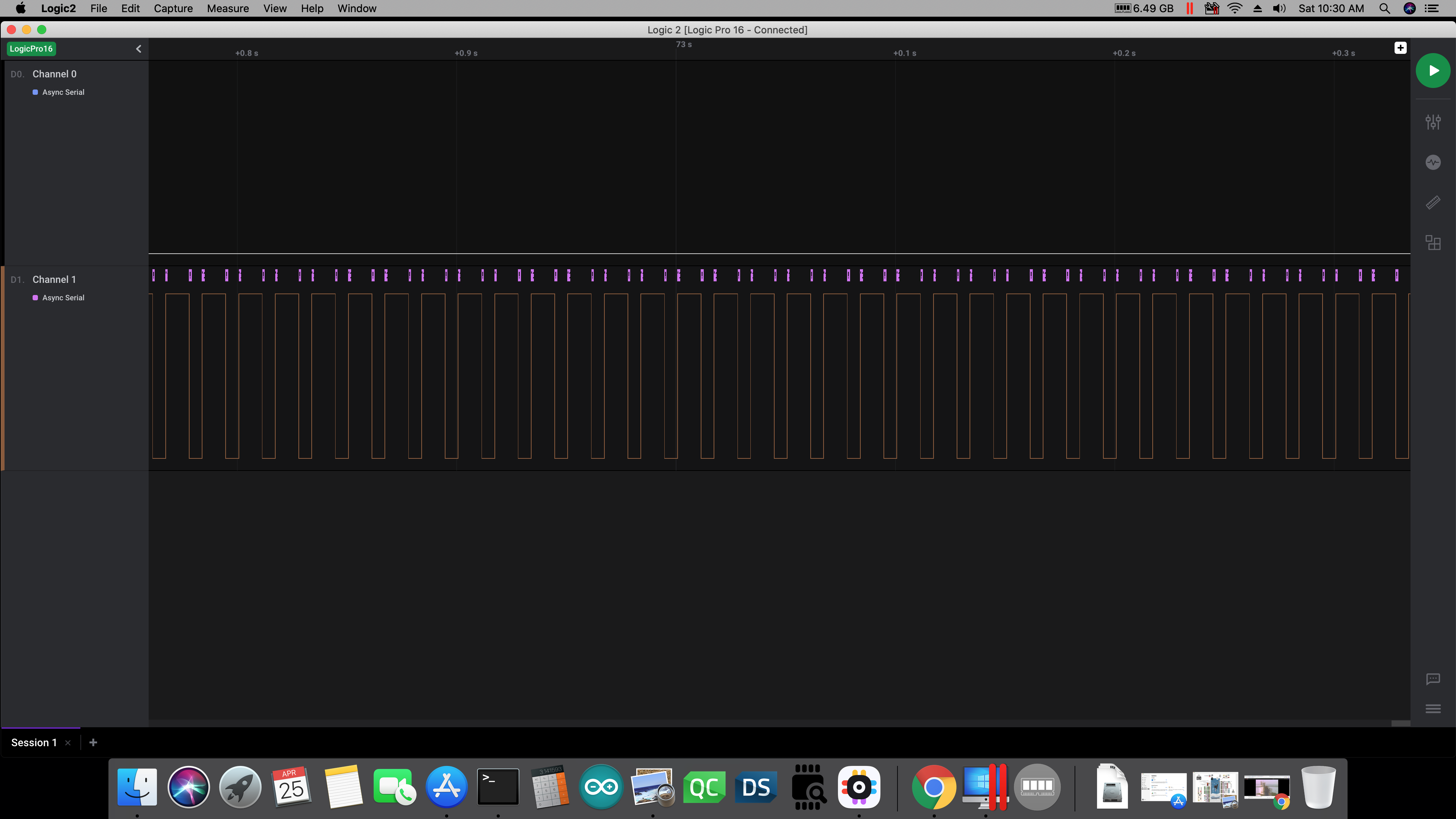
@ansonhe97, that’s exactly opposite from what I found here using a logic analyzer (LA). Here is a screen shot of my trying to send data over Serial1, with the LA on pins 1 & 3 of the 28-header (pins D0/D1):
As you can see, there are indeed characters being sent on the 28-pin header UART pins 1 & 3 (D0/D1). The signal you see in that screen shot was obtained at 9600 baud, on pin 3 of the Arduino header (28-pins), and NOT the Tx pin of the 4-pin header. So there is data being sent on the Arduino header pin 3 (D1), but there are a number of framing errors–which almost suggests that there’s a stop bit problem, as far as I can tell. There are apparently other reasons for a framing error, but one I found mentioned was that there is a problem with the stop bit not being sent correctly.
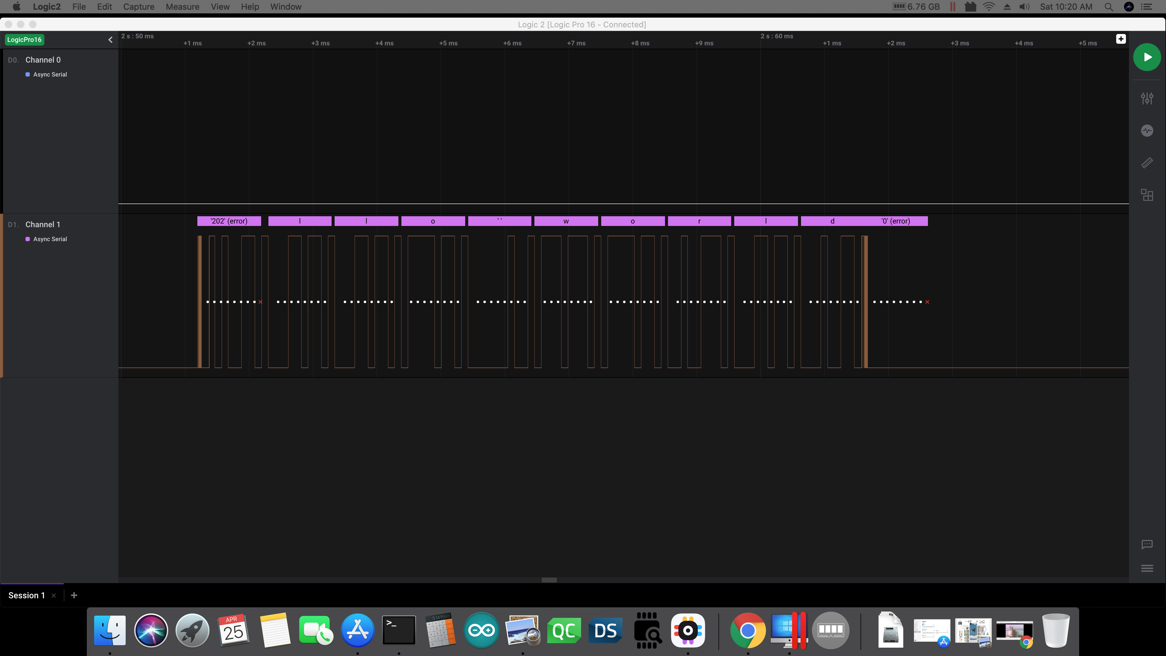
As for the 4-pin header, this screen shot shows what I found with the LA on pin 2 (Tx pin) there:
As you can see, there is a strange semi-symmetrical waveform there. The on-time was around 10 ms, while the off-time was just over 6 ms. So it wasn’t a truly symmetrical waveform, in terms of on/off time. But no matter what I tried sending from my Arduino sketch (one of the examples that comes with the IDE), there is absolutely NO data at all being sent on the 4-pin header. Note that I did not get any sort of traffic on the Rx pin of either header at any time, but I will try to connect a GPS to each of the Rx pins (on both headers) and see what happens then.
The other thing I want to try today is to just put a LA on that 4-pin header without calling Serial1.begin() or SerialUSB.begin() in the code. I didn’t try that the other day when I took these screen shots, and I think it will be interesting to see whether or not that asymmetric square wave is on the 4-pin Tx pin when the UART hasn’t been initialized in code. I will also try these things on a Teensy or Arduino, and to see how things go there. But I’ve never seen that sort of pattern on a UART before–especially one that shows no data being transferred at all.
So like @wx4cb found, my experimentation here shows that Serial1 is on pins 1/3 o the 28-pin header (D0/D1), while pins 1/2 of the 4-pin header don’t seem to do anything. I simply cannot yet explain all the framing errors I found.
Thanks for your response on this issue.
TB
Hello @wx4cb and @ansonhe97…
I did some more experimentation today and tested some working UART code to see if I can read input from the D0 pin of the 28-pin header. In short, I can’t.
This image is taken from my logic analyzer with the probe at on the Tx pin of the Adafruit Ultimate GPS I have used on several projects in the past. You can see in the screen shot the start of the string “$GPRMC,” which is one of the normal GPS data strings. There were many other normal output strings seen as well–in fact the logic analyzer didn’t seem to detect any framing errors from the GPS when read directly.
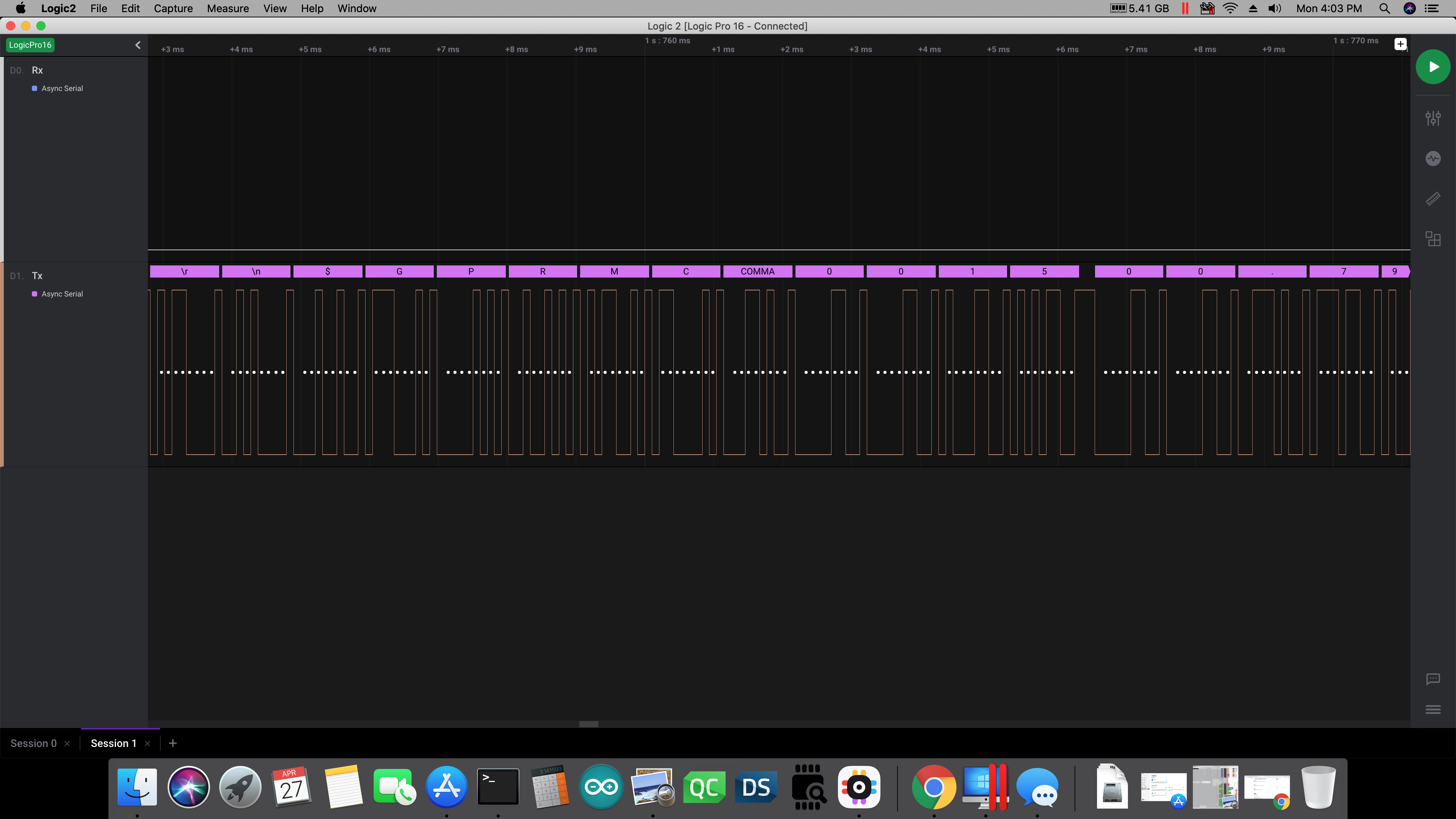
As you can see, there is ASCII data on the Tx pin from the GPS. There was nothing on the Rx pin going to the GPS however, which is exactly the behavior I was expecting to see–as I had the logic analyzer right at the GPS unit. Note that in this image the other LA probe was removed from the Rx pin, which is why that level is LOW; but I did the test many times with both probes attached to the respective pins on the GPS, and got exactly the behavior I was supposed to see. Since I have used this GPS with this code (see below) many times before, I know it all works.
Here is the code that was running on the SAMD21 chip when I grabbed that screen shot:
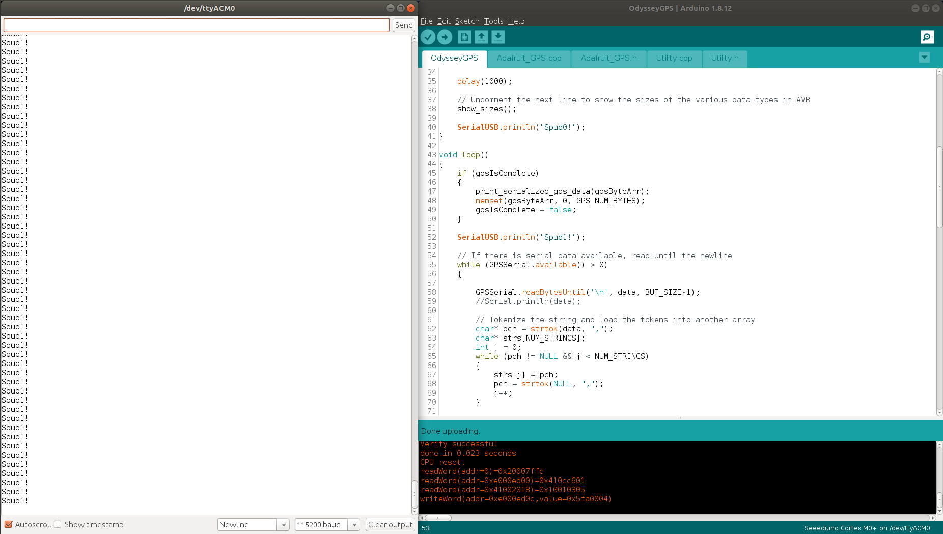
The thing to notice in that image, is the code at line 52–it’s printing that line of output to the SerialUSB output, but then it’s never entering the while loop at line 55. I did have that “Spud1” print call inside the while loop, but moved it back out because it was never getting printed…because the while loop was never getting entered. But the code works with the Teensy I was using right before this–I only had to change all the Serial calls to SerialUSB to run on the Odyssey board. That’s really the only change I had to make. So for whatever reason the call to GPSSerial.available() is returning either a zero or a negative number. It’s certainly NOT returning a positive integer which it should be–especially given the output you see in the previous image.
There are a few other thoughts I had today…
-
Regarding the 4-pin header. This cannot have anything to do with the Arduino’s output of course, because if you need to reset the SAMD chip, you have to momentarily jumper the Tx and Rx pins on that header. So if you have them both attached to some serial device, the chip will be getting reset constantly–and in fact it’s not even available in the Arduino IDE. It just isn’t listed. So other than to reset the SAMD21 chip, it obviously has no other purpose…at least from the perspective of the Arduino user.
-
I uploaded the code from a blank sketch onto the SAMD21 chip today, and re-applied the logic analyzer to the Tx/Rx pins on the 4-pin header. The LA showed the exact same waveform as I saw before (posted in my previous reply above). In other words, the Tx pin shows a semi-symmetric square wave with about 10 ms of ON time, and about 6 ms of OFF time. The Rx pin is always LOW when the Tx pin shows this pattern. The point here is that whatever is going on in the x86 board (BIOS, possibly?), it’s sending that square wave out the Tx pin on that 4-pin header.
-
Overall, I think there is something really screwed up with the serial port functionality on this SAMD21 chip. Not only do I get the behavior I’ve been describing and showing in the screen shots, but another concerning issue I am seeing is that if you try to send a character out the SerialUSB’s Tx pin, nothing happens…until the IDE locks up after the 3rd or 4th attempt. So you then have to force kill the IDE and restart it, and much of the time you have to actually jumper the Tx/Rx pins on the 4-pin header in order to get the SAMD21 chip to respond to programming again. I’ve tried with three different versions of the Arduino IDE (two on Windows, one now in Linux), and get the exact same behavior–pointing to an issue with the board. (Can you confirm this behavior @wx4cb?)
-
Finally, I still can’t explain all the framing errors I have been seeing on Serial1 when I send data from that. In short, the output seen on the SAMD21 Tx line (pin D1) has virtually no uncorrupted data–there are framing errors pretty much everywhere.
So I would like to request that @ansonhe97 address this serial issue, and also provide us with more documentation as to how they’ve implemented this SAMD21 chip in the hardware. I did download the Atmel-SAMD21 datasheet from the link at the bottom of the Getting Started page for the Odyssey board, but haven’t really gone through it yet. I will start looking through it tonight though.
But as far as I can tell, there is most definitely something wrong with the implementation of the Serial1 port on this x86 Odyssey board.
TB
good information to see… what you might want to do is put the LA directly on the samd UART pins and see
I did that too–there’s no difference in behavior. It’s exactly the same as I showed in the previous screen shots I posted. I just didn’t grab new ones of that today as it would be redundant information, and just more information for you to wade through.
I should have mentioned that though, so thanks for reminding me.
TB
Hi all,
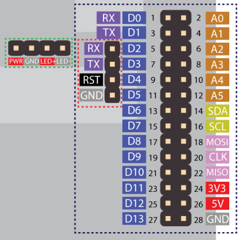
Thanks for investing time to this problem and i have also just tested the problem myself. After some debugging, i have figured this is a big mistake on our half. The pinout diagram was incorrectly labelled and caused all the issues. I have updated the pinout digram on the wiki and bazaar page. Please also check below image for reference.
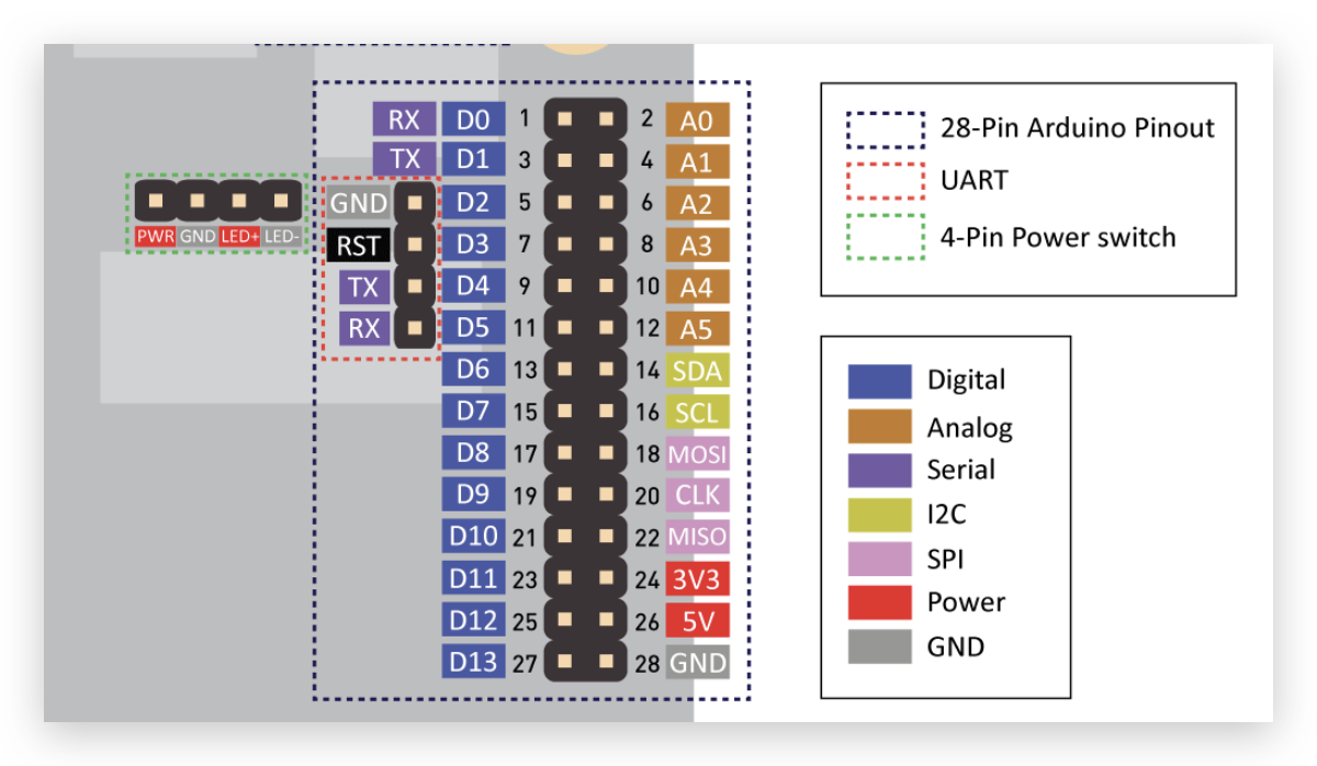
And you were correct, RX and TX on the 4-pin header refer to Serial2 in Arudino, and RX and TX on the 28-pin header refer to Serial1 in Arduino. For more, the USB serial is just Serial.
Sorry for the problems caused and thanks again for spotting out.
Anson
Wow! How did that get so screwed up?!? LOL…
I will test it today with the new pin mapping, but I hope I (we) didn’t screw up anything due to using the wrong pin assignments. It’s also good to see that there will be another UART available (Serial2).
Regarding Serial vs SerialUSB though, @ansonhe97… I have tried to get output using “Serial” on the Arduino IDE serial monitor, and it just didn’t work. The “SerialUSB” object (in code) worked fine. So I can’t necessarily agree with that part of your post–but I will certainly test it again today. But with the test code I was using yesterday, I should be able to test all the serial ports. I am quite shocked though, regarding what you now say is the placing of the voltage rail and ground pins!
The other day I wondered about whether or not the pins were mislabeled on the board, so I went to the Arduino online store and looked at the Zero board. But since it is laid out like the Uno, there really isn’t a way to tell anything for sure as to whether or not the Odyssey board might be mislabeled.
Do you think there is a chance that I have damaged my board through testing, with these incorrect pin assignments? (EDIT: I don’t think so–see below in my next post). I don’t have the old pin assignment diagram to look at on the computer I am writing this on now, but the power rails were NOT in the same location as they are in your current diagram. So I hope I didn’t mess up the GPS either–although I was seeing normal output when I probed it with the logic analyzer yesterday.
Anyway, I’ll test the new pin assignments here and report back a little later today.
Thanks for working on this.
TB
I am testing this again in my electronics lab. Here are today’s findings:
-
I was mistaken when I wondered (in my earlier post today) if the power rail and ground pins changed in position. I see now from the diagram I was using yesterday, that they were where @ansonhe97 has listed them in the new diagram. I was upstairs when I wrote my first post this morning, so I didn’t remember correctly. But I was in fact using the power pins where they were indicated in both the original and the new diagrams. Checking the voltage on both pins now just to be sure, I do read about 3v3 on pin 24, and around 5v on pin 26.
-
There doesn’t seem to be a Serial2 object recognized by the Arduino IDE for the SAMD21 library. I grepped for it under the /home/user/snap directory where the Seeed stuff gets installed by default–but it’s not any source or header file. See the output of grep, here: https://pastebin.com/mQ3N6j3q
That said, it IS in the Arduino core code, in /snap/arduino/. I didn’t post a grep output file as it’s in LOT of places in that directory tree–but the SAMD compiler is apparently not looking there. This brings up a question:
Should we be installing the Arduino SAMD Boards library as well, in the Boards Managers utility in the IDE? I don’t know if the arm-none-eabi-g++ compiler that Seeed Studios has configured for this board is actually looking there…so I thought I should at least ask.
-
SerialUSB IS the serial object we need to be using in order to get output from the Arduino serial monitor. I am positive of that. I’ve tried using the “Serial” object in code many times (including again just now), and there IS NO OUTPUT on the serial monitor. Change all the “Serial” calls to “SerialUSB” and you get output immediately.
-
I strongly suspect that here is still a major issue with the serial functionality of this Odyssey board, in general. Although I no longer seem to lock up the serial monitor after trying to send characters to the board three or four times, I still must force-kill it in Ubuntu. It seems that I can now send characters as many times as I’d like, and the serial monitor (and IDE) continues to function. However when I then try to close the serial monitor using the little ‘X’ button in its upper right corner, the entire IDE locks up. Neither the IDE nor the serial monitor responds after that–and I must force-kill them and start over. I didn’t try this on Windows yet–only Ubuntu. Maybe @wx4cb or someone else can confirm this behavior.
So although I appreciate it that you looked into this issue @ansonhe97, it’s far from being correct. The only thing that I can really see that’s changed is your diagram of the pins on the 4-pin header (swapped Rx/Tx positions), but I cannot test this because the Serial2 object IS NOT recognized by the SAMD21 compiler (arm-none-eabi-g++). Therefore I cannot test and farther.
I am happy to report that placing the logic analyzer on the Rx/Tx pins on the 4-pin header no long causes the board to reset (YAY!!!), and I do NOT see that semi-symmetric square wave signal. I suspect that is because I was actually reading the RST pin signal (LOL!!!), which likely explains the weird waveform I was seeing previously.
TB
Yes–I have saved it on my lab computer, so I was looking at it down there earlier today. That signal is I showed in the screen shot I posted, was coming off the RST pin as it turns out–because that’s the pin that was labeled “TX” in the old diagram. I should have figured that out before he corrected the pin diagram, but there were a number of things going on so I couldn’t quite converge on the problem.
I’ll stand by to hear what @ansonhe97 can find out about the Serial2 pin issue. I suspect there is something missing from the Seeed library that got downloaded in the Arduino IDE, because the ARM compiler being invoked certainly doesn’t know anything about the Serial2 object, as my grep output indicated.
Thanks for working on this.
TB
ok quick sketch pumping out in the loop:
“SerialUSB” is the monitor
“Serial 1” is the D0/D1 pins
“Serial” is the 4 pin header as described.
Now to try input
here’s the code I used:
int i = 0;
void setup() {
// put your setup code here, to run once:
SerialUSB.begin(115200);
Serial.begin(115200);
Serial1.begin(115200);
}
void loop() {
Serial.print(“Serial Loop #”);
Serial.println(i);
Serial1.print(“Serial1 Loop #”);
Serial1.println(i);
SerialUSB.print(“Serial USB Loop #”);
SerialUSB.println(i);
i++;
delay(500);
}
Oh–it’s “Serial” in the 4-pin headers?!? He said Serial2 so that’s what I checked for. But I’d certainly take Serial!
I had a furnace & A/C guy come to the house while I was down in the lab working, so I didn’t get a chance to fully test some things. I also wanted to test my code on a Teensy too, just to “sanity check” it’s behavior there.
Can you reproduce the IDE freeze problem I’m seeing? Try sending characters a bunch of times in the serial monitor text entry field. Then see if the serial monitor (and IDE) locks up either 1) while trying to send additional chars, or 2) when you try to close the serial monitor. Please let me know what you find out.
TB