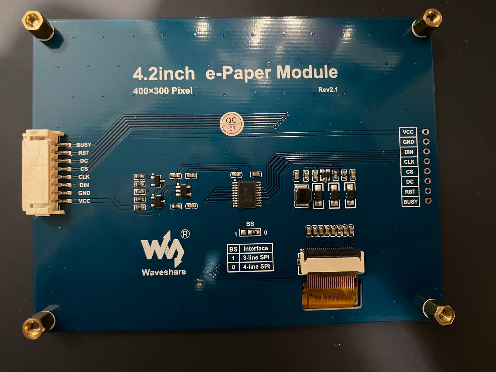
Hey all, I’ve been trying to use the Waveshare 4.2 inch black & white color 4 grayscale module with the Seeeduino Xiao SAMD21 but I can’t seem to get it to work. I’m not sure if it’s the connection, the libraries that I’m using, or something else entirely. I tried using the example that Waveshare provides (https://www.waveshare.com/wiki/4.2inch_e-Paper_Module_Manual#Working_With_Arduino ) for the Arduino. Since the Seeeduino Xiao is Arduino compatible I figured I would only have to reassign a few pins and ensure the DIN and CLK pins were going to where they should. But unfortunately, I haven’t been able to get anything working when running on the Seeeduino Xiao SAMD21. I tested the same program using an Arduino Uno and the example runs with no problems. I even tried it on another Seeeduino Xiao SAMD21 and still no luck.
I also tried using the GxEPD2 library in the following program and it still didn’t work. I was able to get the program working using an ESP32 though.
I’m not sure what I’m missing, or where to look next. I’m new to working with IoT/embedded devices so any insight or help would be greatly appreciated. Thanks.
I tried running both programs that I originally tested with the pin definition from the documentation and nothing worked. Both with and without ‘D’ in the pin declarations. I also tried running the code example from the documentation but it didn’t work either. It appears that the linked device and the code for it are designed to run an e-ink display with that specific hardware attached directly to the e-ink panel and not with any other secondary board connected to the display like the Waveshare e-ink that I have.
I tried that but it didn’t work
I also noticed that when the e-ink display is connected, the Xiao doesn’t show up on any COM ports. I realized this when I tried uploading the code while the display was still connected, and when using Serial.println(); for debugging purposes. Any idea as to why that is?
if it is not showing up on com ports it may be bricked or check the usb cable is power and data and not power only
check your xiao to see if it is working on another sketch (blink for example)
i sudgest this product when experimenting with samd because it includes a reset button
or write a heartbeat into your sketch
with this device you can double click the reset button to go into bootloader mode
also may have to do the manual reset process
unfortunatly this only works on xiao samd not esp32 due to the pogo pin interface
I use the user button to exit program execution, that way the xiao samd is more likely to accept an upload of new code without a bootloader…note exit(0); command
  const int buttonPin = 1;  //the number of the pushbutton pin
  int buttonState = 0;      //variable for reading the pushbutton status

    //Begin Builtin LED Setup
    pinMode(LED_BUILTIN, OUTPUT);//initialize the LED pin as an output
    //End Builtin LED Setup
    //Begin Button Setup
    pinMode(buttonPin, INPUT_PULLUP);//initialize the pushbutton pin as an input
    //End Button Setup

void button_Poll()
  {// Begin Button Poll Function
    // read the state of the pushbutton value
    buttonState = digitalRead(buttonPin);
    // check if the pushbutton is pressed. If it is, the buttonState is High:
    if (buttonState == LOW)
    {
    // Exit Program Execution
    digitalWrite(LED_BUILTIN, HIGH);
    Serial.end();
    exit(0);
    }
  else
    {
    digitalWrite(LED_BUILTIN, LOW);
    }
  }// End Button Poll Function
Hi there,
The code above is missing the Init for the “u8x8.clearDisplay” isn’t going to work without the display driver instantiated, may throw error or may just not run.
my .02
HTH
GL PJ
Hi there,
No you’re not , Sorry the example was for the button code, disregard.
Can You post what code you are using and the lib versions.
It should work with only minor adjustment.
HTH
GL PJ
I’m using the GxEPD2 library, version 1.5.3
Here’s the program.
#include <GxEPD2_BW.h>
#include <Fonts/FreeMonoBold9pt7b.h>
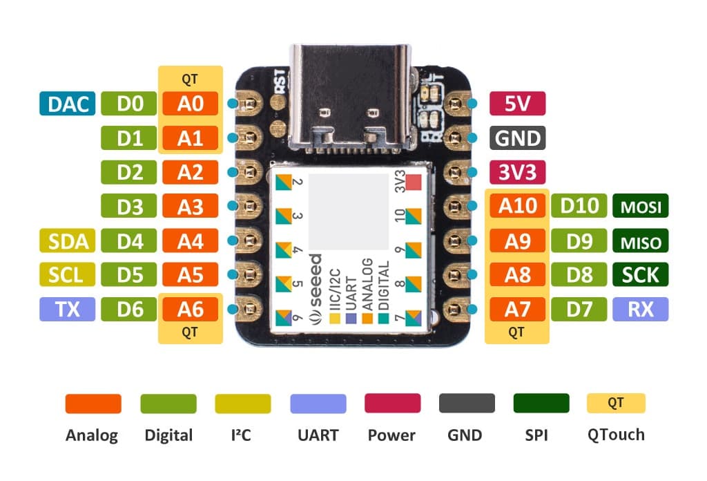
// Pin configuration for Seeeduino Xiao SAMD21
// Display Seeeduino Xiao SAMD21 Pin
// BUSY -> 1
// RST -> 2
// DC -> 3
// CS -> 4
// CLK -> 8
// DIN -> 10
// GND -> GND
// VCC -> 3V3
#define CS_PIN D4
#define DC_PIN D3
#define RST_PIN D2
#define BUSY_PIN D1
GxEPD2_BW<GxEPD2_420, GxEPD2_420::HEIGHT> display(GxEPD2_420(CS_PIN, DC_PIN, RST_PIN, BUSY_PIN));
void setup() {
Serial.begin(9600);
display.init();
}
void loop() {
// For debugging.
Serial.println("First line of super loop.");
display.fillScreen(GxEPD_WHITE);
display.setTextColor(GxEPD_BLACK);
display.setFont(&FreeMonoBold9pt7b);
display.setCursor(10, 50);
display.print("Hello, World!");
display.display();
delay(5000);
display.fillScreen(GxEPD_WHITE);
display.display();
delay(5000);
// For debugging.
Serial.println("Last line of super loop.");
}
I want to note some strange behavior. Whenever the display is plugged into the Xiao, my PC can’t connect to the Xiao. Like there’s no connection to the serial monitor at all and I can’t upload any code. Otherwise, when the e-ink display isn’t connected, it works just fine and I can see the serial output. I know that the Xiao is working and the e-ink display is working as well. I tested both of them separately.
That’s not the case. I only have trouble connecting when the code that I sent is uploaded to the Xiao and the display is connected. When some other code is uploaded to the board (blinking the LED for example) it works fine with the display connected. And conversely, when the code to run the e-ink display is uploaded but the display is not connected, it runs just fine. As in I can see the debugging print statements in the serial monitor. This is the case for two different Xiao boards running the same code.
It’s leading me to think that there’s some hardware-specific setting or library that I missing.
Switch Pin 10 MOSI to Pin 9 MISO (display has NO input)
Master OUT Slave IN, needs to be master IN , SLave OUT. Check that first.
then;
the DC pin is that a VCC pin ? can the Samd21 sync enough to power it?
like that, Nice display too I may have to get one, is it good in sun light , they say they are?
HTH
GL PJ
The documentation specifies that DIN should go to the MOSI pin, not MISO. I tried your suggestion anyway and still got a blank screen. I’m not sure about the DC pin, but based on the documentation, it’s a data/command pin (high for data, low for command).
It is a nice display (when it cooperates with my microcontrollers lol), is sunlight readable, and reasonably priced IMO.
Hi there, So I pulled the trigger can’t beat the price with discount and prime and gift card, LOL,
I think disconnect the C/D line try that?
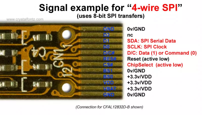
I found this interesting link with a ton of really great info on 3 and 4 wire SPI configurations. worth browse,
4-Wire SPI
In a typical “4-wire SPI” LCD/OLED application the connections will be:
SCK: the SPI ClocK, as usual
SS: the Slave Select, often labeled as CS – – Chip Select
MOSI: the data from the master to the display, usually labeled as SDA (Serial DAta)
C/D: Command /Data
Now you should have been expecting the fourth line to be MISO, so you could read data back from the display–but with LCD controllers, there is a twist.
We need some history to understand the 4th line as used in SPI displays. Traditionally, parallel interface LCD controllers had two registers, a Command register and a Data register. You would write the command to the Command register, then write the appropriate data to the Data register. To select between them, there was a C/D (or A0) line. Set the line to 1=Command or 0=Data then the write the 8 bits of data.
Now back to “4-wire SPI,” the 4th wire is “C/D.” So you can either make an 8-bit SPI write to the display controller’s Command register or an 8-bit SPI write its Data register depending on the state of the C/D line.
Nice! It’s a solid display for (mostly) static image, low-power projects.
Disconnecting the D/C line doesn’t do anything. I was thinking about switching the display to 3-wire SPI mode by bridging one of the contact pads with an SMD resistor but I shouldn’t have to since as I mentioned, the display works perfectly as is with my other microcontrollers. So I’ll read through the page you sent. Been meaning to get into embedded software engineering anyway, so I may as well start here lol. Understanding the workings of SPI (amongst other communication protocols) is quite important from what I hear.
Thanks.
Edit.
Small update: I got the serial output working by disconnecting the RST pin but I’m still not getting any output on the display. The serial monitor is only occasionally printing the print statements from the program I sent. Most of the time it prints “Busy Timeout!”.
So now I can see the serial output and upload code to the Xiao while the display is connected but the RST line needs to be disconnected. I think there might be some incompatibility between the Seeeduino Xiao SAMD21 and the GxEPD2 library. I’ll keep looking for now.