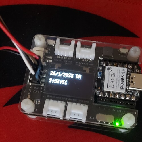
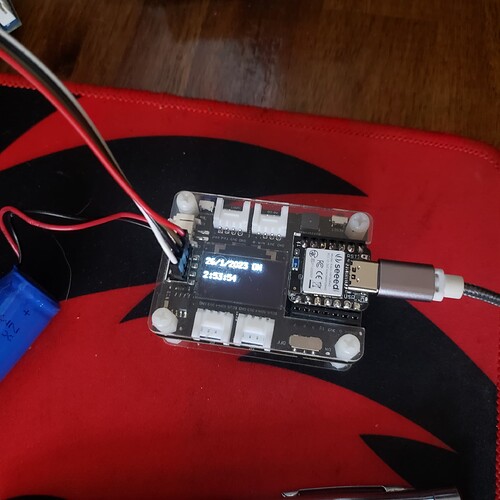
Just to put a bow on this.
I’m using this code to test with … RTC, Display ,Buzzer. Xiao BLE Sense formerly A.K.A. known as the Xiao Nrf52840 BLE Sense. ![]()
saving the compile file sets the initial time and date. if you put a battery in.
// Tweaked by PJG
//Date and time functions using a PCF8563 RTC connected via I2C and Wire lib
#include "RTClib.h"
#include <Wire.h>
#include <U8x8lib.h>
#include <PCF8563.h>
//Works aok.. TESTED PJG 1/26/23 1:54
RTC_PCF8563 rtc;
U8X8_SSD1306_128X64_NONAME_HW_I2C u8x8(/* clock=*/ PIN_WIRE_SCL, /* data=*/ PIN_WIRE_SDA, /* reset=*/ U8X8_PIN_NONE);   // OLEDs without Reset of the Display
PCF8563 pcf;
char daysOfTheWeek[7][12] = {"Sunday", "Monday", "Tuesday", "Wednesday", "Thursday", "Friday", "Saturday"};
int BuzzerPin = A3;           //A3 , P0.29 PIN 4
// use D2 for INT0; attach to CLKOUT pin on RTC
const uint8_t INT_PIN = 2;
int buzzer = BuzzerPin;
// flag to update serial; set in interrupt callback
volatile uint8_t tick_tock = 1;
// INT0 interrupt callback; update tick_tock flag
void set_tick_tock(void) {
  tick_tock = 1;
}
void setup () {
  Serial.begin(115200);
  startsound();
  initdisplay();
  pinMode(BuzzerPin, OUTPUT);
  pinMode(INT_PIN, INPUT);        // set up interrupt pin
  digitalWrite(INT_PIN, HIGH);    // turn on pullup resistors
  // attach interrupt to set_tick_tock callback on rising edge of INT0
  attachInterrupt(digitalPinToInterrupt(INT_PIN), set_tick_tock, RISING);

  if (! rtc.begin()) {
    Serial.println("Couldn't find RTC");
    Serial.flush();
    while (1) delay(10);
  }

  if (rtc.lostPower()) {
    Serial.println("RTC is NOT initialized, let's set the time!");
    // When time needs to be set on a new device, or after a power loss, the
    // following line sets the RTC to the date & time this sketch was compiled
    rtc.adjust(DateTime(F(__DATE__), F(__TIME__)));
    // This line sets the RTC with an explicit date & time, for example to set
    // January 21, 2014 at 3am you would call:
    // rtc.adjust(DateTime(2014, 1, 21, 3, 0, 0));
    //
    // Note: allow 2 seconds after inserting battery or applying external power
    // without battery before calling adjust(). This gives the PCF8523's
    // crystal oscillator time to stabilize. If you call adjust() very quickly
    // after the RTC is powered, lostPower() may still return true.
  }
  // When time needs to be re-set on a previously configured device, the
  // following line sets the RTC to the date & time this sketch was compiled
  // rtc.adjust(DateTime(F(__DATE__), F(__TIME__)));
  // This line sets the RTC with an explicit date & time, for example to set
  // January 21, 2014 at 3am you would call:
  // rtc.adjust(DateTime(2023, 1, 26, 14, 0, 0));

  // When the RTC was stopped and stays connected to the battery, it has
  // to be restarted by clearing the STOP bit. Let's do this to ensure
  // the RTC is running.
  rtc.start();

  // turn on 1Hz clock out, used as INT0 for serial update every second
  rtc.writeSqwPinMode(PCF8563_SquareWave1Hz);
}

void loop () {

  // check if time display should be output
  if(tick_tock) {

    DateTime now = rtc.now();

    char time_format[] = "hh:mm:ss AP";
    char date_format[] = "MM/DD/YYYY";

    Serial.println(now.toString(time_format));
    Serial.println(now.toString(date_format));
    Serial.println();

    tick_tock = 0;

  }
  Time nowTime = pcf.getTime();//get current time
  //u8x8.setFont(u8x8_font_chroma48medium8_r);   // choose a suitable font
  u8x8.setCursor(0, 0);
  u8x8.print(nowTime.day);
  u8x8.print("/");
  u8x8.print(nowTime.month);
  u8x8.print("/");
  u8x8.print("20");
  u8x8.print(nowTime.year);
  u8x8.setCursor(0, 3);
  u8x8.print(nowTime.hour - 12);
  u8x8.print(":");
  u8x8.print(nowTime.minute);
  u8x8.print(":");
  u8x8.println(nowTime.second);
 delay(1000);

}

// ----func's----
//
void startsound() {
  tone (buzzer, 890);
    delay (220);
    noTone(buzzer);
    delay (20);
    tone (buzzer, 800);
    delay (220);
    noTone(buzzer);
    delay (20);
    tone (buzzer, 800);
    delay (220);
    noTone(buzzer);
    delay (20);
    tone (buzzer, 990);
    delay (420);
    noTone(buzzer);
    delay (20);
}

void initdisplay() {
  u8x8.begin();
    u8x8.setFlipMode(1);   // set number from 1 to 3, the screen word will rotary 180
    u8x8.setFont(u8x8_font_8x13B_1x2_r);
    u8x8.clearDisplay();
    u8x8.setCursor(4, 0);
    u8x8.print("Power ON ");
}
getting this Serial Output.
02:52:16 PM
01/26/2023
display is this on dev board…
HTH, GL :-p

