Seeeduino XIAO Expansion board RTC example doesn't set the time properly in the PCF8563

I’ve started with the Seeduino XIAO Expansion board + a XIAO BLE and I am working with the sample code here , nearly unmodified:

The modifications I have made are related to the current date/time. Regardless of the date used, the values come out corrupted:

45/25/20165
45:65:65

(visual display shows this, also I tried adding print statements to see if this is really just a display issue, but the values are also corrupted). I haven’t yet reviewed the library or the datasheet for the PCF8563. Is this a problem with a fried RTC? Do I have to have the battery in my clock? I assumed it would work without the battery. Something else, wrong library version (RTC library appears to be now 4 years old).

Please advise on what the problem might be in this case.

Thanks.

See U8G2 FAQ on Github. Here is the pertinent section (First question) :

Q: Why does my xxx_SW_I2C() device not work with my other I2C devices?
A: SW_I2C emulates I2C with digitalWrite(), which will have a conflict with other
I2C devices at the same pins. There are two options: (A) use xxx_HW_I2C() or
(B) use different pins with xxx_SW_I2C()

The RTC and OLED are both on the same I2C bus.
If I switch the U8G2 OLED device to

U8X8_SSD1306_128X64_NONAME_HW_I2C u8x8(/* reset=*/ U8X8_PIN_NONE);

both the display and the OLED work on my expansion board with the XIAO (not BLE.)

Agree with @ricksorensen:
For test purposes, for my XIAO BLE Sense on the XIAO expansion board, I made the following change to the sketch from the Wiki:

//U8X8_SSD1306_128X64_NONAME_SW_I2C u8x8(/* clock=*/ SCL, /* data=*/ SDA, /* reset=*/ U8X8_PIN_NONE);   // OLEDs without Reset of the Display
U8X8_SSD1306_128X64_NONAME_HW_I2C u8x8(/* reset=*/ U8X8_PIN_NONE);

With no other changes, the output looks as expected (ugly, but can be “fixed” once you see it doing what it’s supposed to do).

Bottom line to the OP, if you post your “slightly modified” sketch, maybe we can verify.

Regards,

Dave

Footnote: I did not and will not connect a battery to the XIAO expansion board with anything other than an original XIAO plugged in. It’s not designed to accommodate the charging circuitry on boards like the BLE. (Haven’t looked very carefully, but I’m not taking chances.)

1 Like

Slightly modified code, as I said, just the code (I experimented with different values punched into the dat, year, minut, etc.

#include <PCF8563.h>

#include <Arduino.h>
#include <U8x8lib.h>
PCF8563 pcf;
#include <Wire.h>
 
U8X8_SSD1306_128X64_NONAME_SW_I2C u8x8(/* clock=*/ SCL, /* data=*/ SDA, /* reset=*/ U8X8_PIN_NONE);   // OLEDs without Reset of the Display


void setup() {
  Serial.begin(115200);
  u8x8.begin();
  u8x8.setFlipMode(1);
  Wire.begin();


  pcf.init();//initialize the clock
  pcf.stopClock();//stop the clock
  pcf.setYear(20);//set year
  pcf.setMonth(10);//set month
  pcf.setDay(23);//set dat
  pcf.setHour(17);//set hour
  pcf.setMinut(33);//set minut
  pcf.setSecond(0);//set second
  pcf.startClock();//start the clock

}
 
void loop() {
  Time nowTime = pcf.getTime();//get current time
  u8x8.setFont(u8x8_font_chroma48medium8_r);   // choose a suitable font
 
  u8x8.setCursor(0, 0);


  u8x8.print(nowTime.day);
  u8x8.print("/");
  u8x8.print(nowTime.month);
  u8x8.print("/");
  u8x8.print("20");
  u8x8.print(nowTime.year);
  u8x8.setCursor(0, 1);
  u8x8.print(nowTime.hour);
  u8x8.print(":");
  u8x8.print(nowTime.minute);
  u8x8.print(":");
  u8x8.println(nowTime.second);

  delay(1000);
}

I will review this faq … have not seen this section on the U8G2 GH.

Your code does not compile for me. Are you sure you have your Arduino setup for your XIAO BLE board is consistent with the information in its Wiki:

I get compiler errors with your code from the Expansion board Wiki: Here are the significant lines from the error messages:

Arduino: 1.8.19 (Windows 10), TD: 1.56, Board: "Seeed XIAO nRF52840 Sense"

Forum_RTC:8:52: error: 'SCL' was not declared in this scope
 U8X8_SSD1306_128X64_NONAME_SW_I2C u8x8(/* clock=*/ SCL, /* data=*/ SDA, /* reset=*/ U8X8_PIN_NONE);   // OLEDs without Reset of the Display
                                                    ^~~

Forum_RTC:8:68: error: 'SDA' was not declared in this scope
 U8X8_SSD1306_128X64_NONAME_SW_I2C u8x8(/* clock=*/ SCL, /* data=*/ SDA, /* reset=*/ U8X8_PIN_NONE);   // OLEDs without Reset of the Display

In particular:
In your Board Manager did you install “Seeed nrf52840 Boards” version 2.6.1?

Did you select Tools->Board->Arduino Mbed OS Boards->Seeed XIAO nRF52840 Sense ?

The pins_arduino.h file in the variants directory for this board does not define SCL or SDA.
You could try defining them in you sketch before the code that actually instantiates the u8x8 object, but instead of that did you make the changes that we previously suggested?

Namely: The Wiki code uses Software I2C and our suggested modification uses Hardware I2C. (See Footnote)

//U8X8_SSD1306_128X64_NONAME_SW_I2C u8x8(/* clock=*/ SCL, /* data=*/ SDA, /* reset=*/ U8X8_PIN_NONE);   // OLEDs without Reset of the Display
U8X8_SSD1306_128X64_NONAME_HW_I2C u8x8(/* reset=*/ U8X8_PIN_NONE);

Regards,

Dave

Footnote:
The reason I don’t muck around with the U8g2 Software I2C on a Seeed board is that once upon a time (in a galaxy far, far away) I tried it and it didn’t work for me regardless of SDA and SCL assignments. (Maybe it works now, but I have no reason to spend time trying something that I don’t intend to use.)

Update: I know I said that I had no reason to test something that I probably won’t use, but sometimes I just can’t help myself.

So…

I ran the (unmodified) code from the Expansion board Wiki on a XIAO (original XIAO, not BLE Sense) and got bad output on the screen along the lines of your original post.

The very first time through the loop, when it read back the time from the RTC, it got back exactly what was written in setup().

Subsequent reads all gave values similar to those of your first post (My first line was the same as yours, Your second line was 45:65:65; I got 45:85:85)

I added code to print the individual time values:

void printTime(const Time & now)
{
  static int pass = 1;
  Serial.print("\nPass ");Serial.println(pass++); 
  Serial.print("Day    = ");Serial.println(now.day);
  Serial.print("Month  = ");Serial.println(now.month);
  Serial.print("Year   = ");Serial.println(now.year);
  Serial.print("Hour   = ");Serial.println(now.hour);
  Serial.print("Minute = ");Serial.println(now.minute);
  Serial.print("Second = ");Serial.println(now.second);
}

Then in loop():

void loop() {
  Time nowTime = pcf.getTime();//get current time
  printTime(nowTime);
.
. // All of the original code in the Wiki example
.
}

Output was:

Pass 1
Day    = 23
Month  = 10
Year   = 20
Hour   = 17
Minute = 33
Second = 0

Pass 2
Day    = 45
Month  = 25
Year   = 165
Hour   = 45
Minute = 85
Second = 85

Pass 3
Day    = 45
Month  = 25
Year   = 165
Hour   = 45
Minute = 85
Second = 85

Values did not change for additional passes through the loop.

Final note: The exact same code (using Hardware I2C) ran on an XIAO and an XIAO BLE board.

Conclusion: The graphics library Software I2C is not compatible with XIAO. It may (or, maybe, not) work with other boards and other CPUs, but the Wiki code simply doesn’t work with current board code and current library code. Period Full stop.

Regards,

Dave

Footnote
Sometimes I just can’t help myself. Really!

So my configuration required, per the wiki, integration of the PDCF8563 library and the U8x8lib, so my apologies, the example doesn’t work directly out of the box without using the library manager for the sketch or modifying the tool’s Arduino library folder.

Regarding Tools->Board, I installed and use “SEEED SAMD Boards”->SEEED XIAO , not specifically mbedOS, and no reference to NRF52840. Maybe a mistake on my end. . https://files.seeedstudio.com/arduino/package_seeeduino_boards_index.json . I am on a Mac so I am certain there are a few differences in the presentation of the interface.

Regarding your findings, thank you for investigating.

The XIAO and the XIAO BLE Sense module use different CPUs and are quite different in operation. Both are supported in the Arduino IDE, but you gotta select the right one. No manual modification of the Arduino library folder (or anything else) if you follow the instructions on the XIAO BLE Sense Wiki that I pointed you to in my previous post. Use Arduino’s Boards Manager and Libraries Manager.

I didn’t make this stuff up. Just went along with the program. See Footnote.

Anyhow, the Wiki shows screen shots, so I won’t bother to attach my own, but here’s the drill:

  1. Add the link to the seeeduino boards .json file in the File-Preferences window. If you already have other stuff in the “Additional boards Manager URLs:” entry, put in a comma and the new link.

  2. You may (or, maybe, not) have to leave Arduino and come back in to see the effect. Then in the Tools->Board->Board Manager… window, search for “seeed nrf52” and click on “Install”

  3. You may (or, maybe, not) have to leave Arduino and come back to see the effect. Then under Tools->Board->Arduino Mbed OS Boards select Seeed XIAO nRF52840 Sense

Conclusion (so far): I found that the information XIAO BLE Sense Wiki page to be completely adequate.

Then, on the XIAO Expansion board Wiki, the example did not work as posted. Changing the object to use Hardware I2c instead of Software I2C brought expected results.

It crossed my mind that, since the Expansion board Wiki was written for the XIAO, not the XIAO BLE, maybe that was the problem. In fact, as I discovered, it the wiki code compiled without errors for the XIAO, but didn’t work. Changing to Hardware I2C worked for both boards.

Bottom line: Does it work for you after changing the board selection and changing the single line of code that I showed in the sketch? How about my test code that I attached to the previous post?

Regards,

Dave

Footnote:
No one was born knowing this stuff, you know.

Dear Dave,
I am desperately looking for some documentation about the deep sleep and intrupt and other stuff for xiao ble sense, I have found your comment here, actually, I have the same issue, I have followed the wiki and I do not have Seeed XIAO nRF52840 Sense under Arduino Mbed OS Boards menu !! It is under Seeed nRF Boards!
I attached the screenshots of my Arduino IDE, t, any idea what is the issue? I have Arduino 1.18.16 and the latest seeed libs and (https://files.seeedstudio.com/arduino/package_seeeduino_boards_index.json)
I appreciate your answer.
Thanks


I wish I could help more. I can only report what works for me. (Previously used Arduino 1.8.16 on Windows 10 after operating a long time with older versions. Just updated to Arduino 1.8.19 with no obviously visible or functional changes to the several older projects I had archived.)

Please note: I have no connections to or insight into the workings at Seeed.

I have been annoyed at the very numerous Wiki and other software documentation that just flat doesn’t work.

Sometimes it’s minor (if you know certain secrets of Arduino)

Sometimes it’s major (invalid updates to Seeed board packages that break things that used to work).

Sometimes it’s just plain ignorance on the part of developers who are, I’m sure, very nice people, but who (obviously?) haven’t worked in a commercial (or even advanced “hobbyist”) environment.

And, in particular, what seems to be a lack of control of the software release process (Design review by someone other than the developer (someone with commercial experience)? Regression testing?)

Bottom line: I keep coming back to Seeed because some of their hardware seems ready to accommodate my needs (and sometimes suits my fancy).

Sorry I can’t go farther with this topic. I’ve pretty much shot my wad.

Regards,

Dave

1 Like

Thanks - this seemed to have uncovered a flaw in my set up. I now recall that I set up originally with a regular XIAO (not BLE) and maybe didn’t finish / follow the XIAO BLE set up per the wiki. I’ll run through this again, since I am specifically in this for the BLE, although I happen to have both boards.

I’ll review tonight after I finish a few other projects .

Verifying, that with a XIAO BLE SENSE board, with the above code mods suggested by @davekw7x.

Also verifying, the XIAO and XIAO BLE SENSE look identical. Why is this a problem… because it leads to confusion by careless people. At some point I put the XIAO on the expansion board thinking it was the BLE SENSE. So there is no way the BLE SENSE board will compile with the board set to XIAO. Confirming the XIAO works as well with the suggested change, no unusual output. Thanks to all who commented.

1 Like

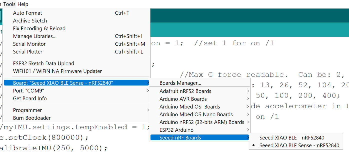
Just to put a bow on this.
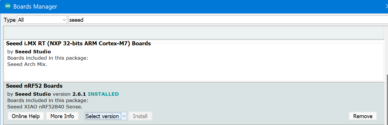
I’m using this code to test with … RTC, Display ,Buzzer. Xiao BLE Sense formerly A.K.A. known as the Xiao Nrf52840 BLE Sense. :slight_smile:
saving the compile file sets the initial time and date. if you put a battery in.

// Tweaked by PJG
//Date and time functions using a PCF8563 RTC connected via I2C and Wire lib
#include "RTClib.h"
#include <Wire.h>
#include <U8x8lib.h>
#include <PCF8563.h>
//Works aok.. TESTED PJG 1/26/23 1:54
RTC_PCF8563 rtc;
U8X8_SSD1306_128X64_NONAME_HW_I2C u8x8(/* clock=*/ PIN_WIRE_SCL, /* data=*/ PIN_WIRE_SDA, /* reset=*/ U8X8_PIN_NONE);   // OLEDs without Reset of the Display
PCF8563 pcf;
char daysOfTheWeek[7][12] = {"Sunday", "Monday", "Tuesday", "Wednesday", "Thursday", "Friday", "Saturday"};
int BuzzerPin = A3;           //A3 , P0.29 PIN 4
// use D2 for INT0; attach to CLKOUT pin on RTC
const uint8_t INT_PIN = 2;
int buzzer = BuzzerPin;
// flag to update serial; set in interrupt callback
volatile uint8_t tick_tock = 1;
// INT0 interrupt callback; update tick_tock flag
void set_tick_tock(void) {
  tick_tock = 1;
}
void setup () {
  Serial.begin(115200);
  startsound();
  initdisplay();
  pinMode(BuzzerPin, OUTPUT);
  pinMode(INT_PIN, INPUT);        // set up interrupt pin
  digitalWrite(INT_PIN, HIGH);    // turn on pullup resistors
  // attach interrupt to set_tick_tock callback on rising edge of INT0
  attachInterrupt(digitalPinToInterrupt(INT_PIN), set_tick_tock, RISING);

  if (! rtc.begin()) {
    Serial.println("Couldn't find RTC");
    Serial.flush();
    while (1) delay(10);
  }

  if (rtc.lostPower()) {
    Serial.println("RTC is NOT initialized, let's set the time!");
    // When time needs to be set on a new device, or after a power loss, the
    // following line sets the RTC to the date & time this sketch was compiled
    rtc.adjust(DateTime(F(__DATE__), F(__TIME__)));
    // This line sets the RTC with an explicit date & time, for example to set
    // January 21, 2014 at 3am you would call:
    // rtc.adjust(DateTime(2014, 1, 21, 3, 0, 0));
    //
    // Note: allow 2 seconds after inserting battery or applying external power
    // without battery before calling adjust(). This gives the PCF8523's
    // crystal oscillator time to stabilize. If you call adjust() very quickly
    // after the RTC is powered, lostPower() may still return true.
  }
  // When time needs to be re-set on a previously configured device, the
  // following line sets the RTC to the date & time this sketch was compiled
  // rtc.adjust(DateTime(F(__DATE__), F(__TIME__)));
  // This line sets the RTC with an explicit date & time, for example to set
  // January 21, 2014 at 3am you would call:
  // rtc.adjust(DateTime(2023, 1, 26, 14, 0, 0));

  // When the RTC was stopped and stays connected to the battery, it has
  // to be restarted by clearing the STOP bit. Let's do this to ensure
  // the RTC is running.
  rtc.start();

  // turn on 1Hz clock out, used as INT0 for serial update every second
  rtc.writeSqwPinMode(PCF8563_SquareWave1Hz);
}

void loop () {

  // check if time display should be output
  if(tick_tock) {

    DateTime now = rtc.now();

    char time_format[] = "hh:mm:ss AP";
    char date_format[] = "MM/DD/YYYY";

    Serial.println(now.toString(time_format));
    Serial.println(now.toString(date_format));
    Serial.println();
  
    tick_tock = 0;

  }
  Time nowTime = pcf.getTime();//get current time
  //u8x8.setFont(u8x8_font_chroma48medium8_r);   // choose a suitable font
  u8x8.setCursor(0, 0);
  u8x8.print(nowTime.day);
  u8x8.print("/");
  u8x8.print(nowTime.month);
  u8x8.print("/");
  u8x8.print("20");
  u8x8.print(nowTime.year);
  u8x8.setCursor(0, 3);
  u8x8.print(nowTime.hour - 12);
  u8x8.print(":");
  u8x8.print(nowTime.minute);
  u8x8.print(":");
  u8x8.println(nowTime.second);
 delay(1000);

}

// ----func's----
//
void startsound() {
  tone (buzzer, 890);
    delay (220);
    noTone(buzzer);
    delay (20);
    tone (buzzer, 800);
    delay (220);
    noTone(buzzer);
    delay (20);
    tone (buzzer, 800);
    delay (220);
    noTone(buzzer);
    delay (20);
    tone (buzzer, 990);
    delay (420);
    noTone(buzzer);
    delay (20);
}

void initdisplay() {
  u8x8.begin();
    u8x8.setFlipMode(1);   // set number from 1 to 3, the screen word will rotary 180
    u8x8.setFont(u8x8_font_8x13B_1x2_r);
    u8x8.clearDisplay();
    u8x8.setCursor(4, 0);
    u8x8.print("Power ON ");
}

getting this Serial Output.

02:52:16 PM
01/26/2023

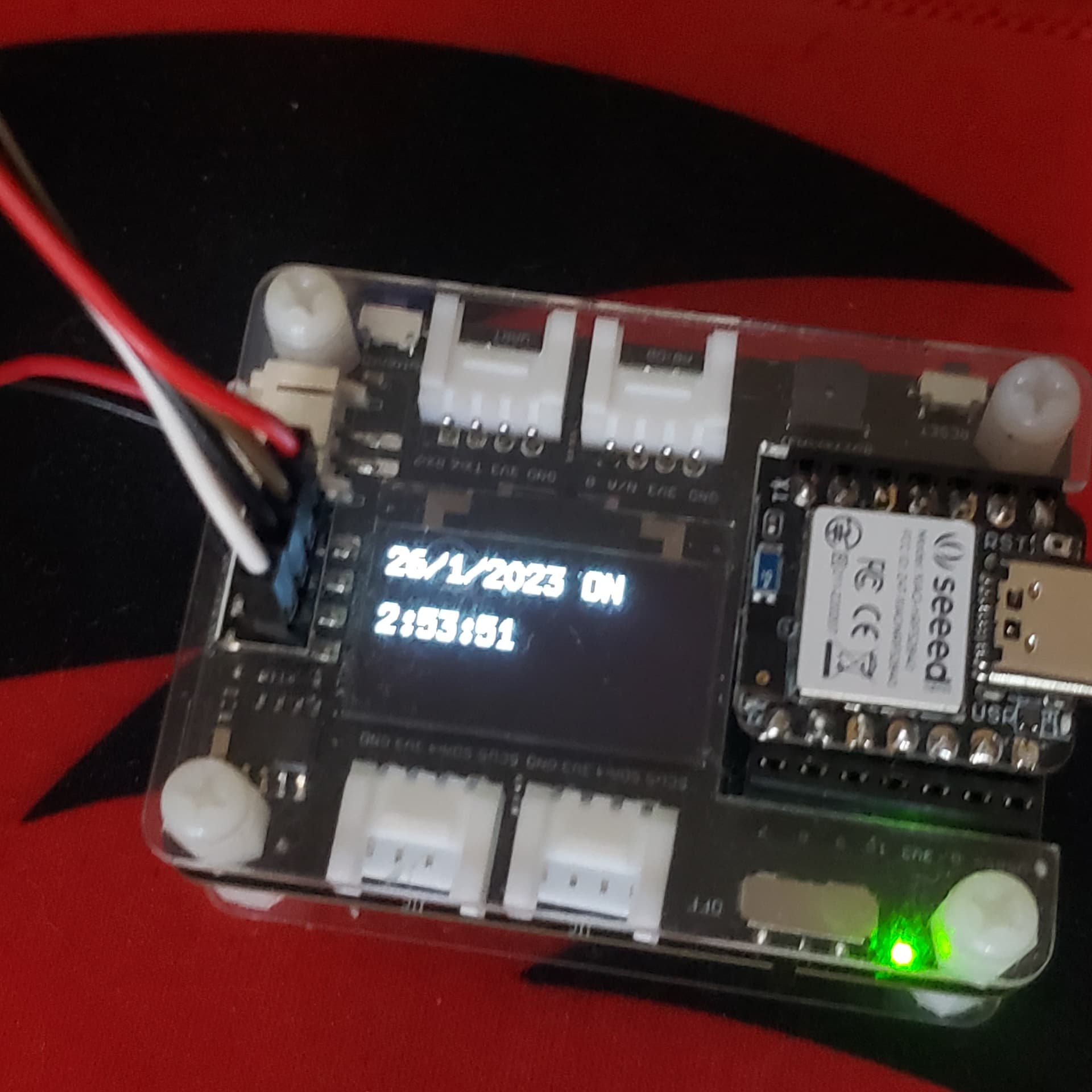
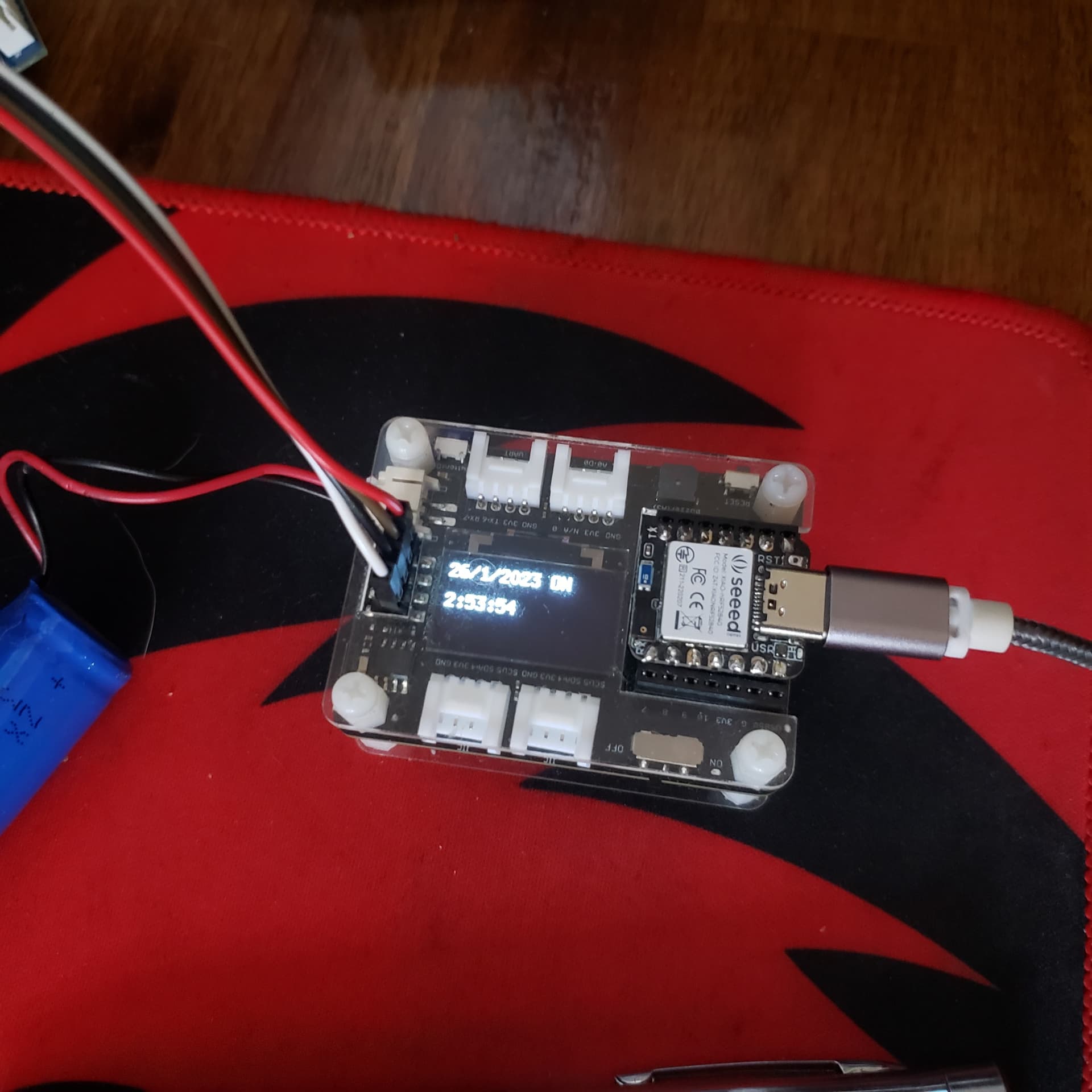
display is this on dev board…


HTH, GL :-p