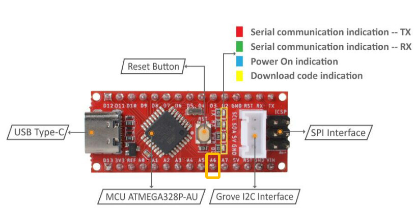
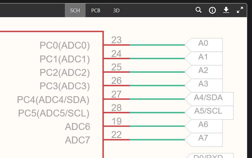
Hi Folks - I picked up a Seeeduino Nano and a Grove WS2813 RGB Strip. I thought this might be a nice combo to do some experiments with RGB lighting given the price of each. I am struggling with set up. I have looked at FastLED library as well as a few others. I am a bit perplexed as to what value to use for the CLOCK and DATA pins. If I use the Grove connector, this should be A4 and A5. Can anyone clarify. I was not able to get any LEDs to light up on the strip. I looked through the schematic and these connectors correspond with 28 and 27. Any assistance on the correct value to use for this strip + a nano. Thanks. I have wrestled with this but I cannot get lights.
/// @file Blink.ino
/// @brief Blink the first LED of an LED strip
/// @example Blink.ino
#include <FastLED.h>
// How many leds in your strip?
#define NUM_LEDS 1
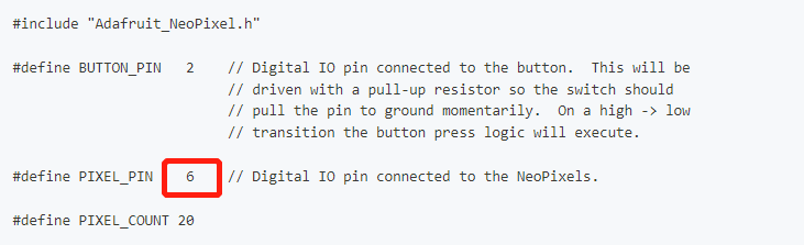
// For led chips like WS2812, which have a data line, ground, and power, you just
// need to define DATA_PIN. For led chipsets that are SPI based (four wires - data, clock,
// ground, and power), like the LPD8806 define both DATA_PIN and CLOCK_PIN
// Clock pin only needed for SPI based chipsets when not using hardware SPI
#define DATA_PIN 3
#define CLOCK_PIN 13
// Define the array of leds
CRGB leds[NUM_LEDS];
void setup() {
// Uncomment/edit one of the following lines for your leds arrangement.
// ## Clockless types ##
FastLED.addLeds<NEOPIXEL, DATA_PIN>(leds, NUM_LEDS); // GRB ordering is assumed
// FastLED.addLeds<SM16703, DATA_PIN, RGB>(leds, NUM_LEDS);
// FastLED.addLeds<TM1829, DATA_PIN, RGB>(leds, NUM_LEDS);
// FastLED.addLeds<TM1812, DATA_PIN, RGB>(leds, NUM_LEDS);
// FastLED.addLeds<TM1809, DATA_PIN, RGB>(leds, NUM_LEDS);
// FastLED.addLeds<TM1804, DATA_PIN, RGB>(leds, NUM_LEDS);
// FastLED.addLeds<TM1803, DATA_PIN, RGB>(leds, NUM_LEDS);
// FastLED.addLeds<UCS1903, DATA_PIN, RGB>(leds, NUM_LEDS);
// FastLED.addLeds<UCS1903B, DATA_PIN, RGB>(leds, NUM_LEDS);
// FastLED.addLeds<UCS1904, DATA_PIN, RGB>(leds, NUM_LEDS);
// FastLED.addLeds<UCS2903, DATA_PIN, RGB>(leds, NUM_LEDS);
// FastLED.addLeds<WS2812, DATA_PIN, RGB>(leds, NUM_LEDS); // GRB ordering is typical
// FastLED.addLeds<WS2852, DATA_PIN, RGB>(leds, NUM_LEDS); // GRB ordering is typical
// FastLED.addLeds<WS2812B, DATA_PIN, RGB>(leds, NUM_LEDS); // GRB ordering is typical
// FastLED.addLeds<GS1903, DATA_PIN, RGB>(leds, NUM_LEDS);
// FastLED.addLeds<SK6812, DATA_PIN, RGB>(leds, NUM_LEDS); // GRB ordering is typical
// FastLED.addLeds<SK6822, DATA_PIN, RGB>(leds, NUM_LEDS);
// FastLED.addLeds<APA106, DATA_PIN, RGB>(leds, NUM_LEDS);
// FastLED.addLeds<PL9823, DATA_PIN, RGB>(leds, NUM_LEDS);
// FastLED.addLeds<SK6822, DATA_PIN, RGB>(leds, NUM_LEDS);
// FastLED.addLeds<WS2811, DATA_PIN, RGB>(leds, NUM_LEDS);
// FastLED.addLeds<WS2813, DATA_PIN, RGB>(leds, NUM_LEDS);
// FastLED.addLeds<APA104, DATA_PIN, RGB>(leds, NUM_LEDS);
// FastLED.addLeds<WS2811_400, DATA_PIN, RGB>(leds, NUM_LEDS);
// FastLED.addLeds<GE8822, DATA_PIN, RGB>(leds, NUM_LEDS);
// FastLED.addLeds<GW6205, DATA_PIN, RGB>(leds, NUM_LEDS);
// FastLED.addLeds<GW6205_400, DATA_PIN, RGB>(leds, NUM_LEDS);
// FastLED.addLeds<LPD1886, DATA_PIN, RGB>(leds, NUM_LEDS);
// FastLED.addLeds<LPD1886_8BIT, DATA_PIN, RGB>(leds, NUM_LEDS);
// ## Clocked (SPI) types ##
// FastLED.addLeds<LPD6803, DATA_PIN, CLOCK_PIN, RGB>(leds, NUM_LEDS); // GRB ordering is typical
// FastLED.addLeds<LPD8806, DATA_PIN, CLOCK_PIN, RGB>(leds, NUM_LEDS); // GRB ordering is typical
// FastLED.addLeds<WS2801, DATA_PIN, CLOCK_PIN, RGB>(leds, NUM_LEDS);
// FastLED.addLeds<WS2803, DATA_PIN, CLOCK_PIN, RGB>(leds, NUM_LEDS);
// FastLED.addLeds<SM16716, DATA_PIN, CLOCK_PIN, RGB>(leds, NUM_LEDS);
// FastLED.addLeds<P9813, DATA_PIN, CLOCK_PIN, RGB>(leds, NUM_LEDS); // BGR ordering is typical
// FastLED.addLeds<DOTSTAR, DATA_PIN, CLOCK_PIN, RGB>(leds, NUM_LEDS); // BGR ordering is typical
// FastLED.addLeds<APA102, DATA_PIN, CLOCK_PIN, RGB>(leds, NUM_LEDS); // BGR ordering is typical
// FastLED.addLeds<SK9822, DATA_PIN, CLOCK_PIN, RGB>(leds, NUM_LEDS); // BGR ordering is typical
}
void loop() {
// Turn the LED on, then pause
leds[0] = CRGB::Red;
FastLED.show();
delay(500);
// Now turn the LED off, then pause
leds[0] = CRGB::Black;
FastLED.show();
delay(500);
}