Seeed XIAO BLE nRF52840 Sense giving bad gyroscope data

Hello all

im using the IMU on the Seeed XIAO BLE nRF52840 Sense to read gyroscope data, however the data returned seems to be bad, even while resting:

While running the sample code

#include "LSM6DS3.h"
#include "Wire.h"

//Create a instance of class LSM6DS3
LSM6DS3 myIMU(I2C_MODE, 0x6A);    //I2C device address 0x6A

void setup() {
    // put your setup code here, to run once:
    Serial.begin(9600);
    while (!Serial);
    //Call .begin() to configure the IMUs
    if (myIMU.begin() != 0) {
        Serial.println("Device error");
    } else {
        Serial.println("Device OK!");
    }
}

void loop() {
    //Accelerometer
    Serial.print("\nAccelerometer:\n");
    Serial.print(" X1 = ");
    Serial.println(myIMU.readFloatAccelX(), 4);
    Serial.print(" Y1 = ");
    Serial.println(myIMU.readFloatAccelY(), 4);
    Serial.print(" Z1 = ");
    Serial.println(myIMU.readFloatAccelZ(), 4);

    //Gyroscope
    Serial.print("\nGyroscope:\n");
    Serial.print(" X1 = ");
    Serial.println(myIMU.readFloatGyroX(), 4);
    Serial.print(" Y1 = ");
    Serial.println(myIMU.readFloatGyroY(), 4);
    Serial.print(" Z1 = ");
    Serial.println(myIMU.readFloatGyroZ(), 4);

    //Thermometer
    Serial.print("\nThermometer:\n");
    Serial.print(" Degrees C1 = ");
    Serial.println(myIMU.readTempC(), 4);
    Serial.print(" Degrees F1 = ");
    Serial.println(myIMU.readTempF(), 4);

    delay(1000);
}

i get this returned

-> 
00:46:41.064 -> Accelerometer:
00:46:41.064 ->  X1 = 0.0337
00:46:41.064 ->  Y1 = -0.2913
00:46:41.064 ->  Z1 = 0.9833
00:46:41.110 -> 
00:46:41.110 -> Gyroscope:
00:46:41.110 ->  X1 = -0.3500
00:46:41.110 ->  Y1 = -2.5900
00:46:41.110 ->  Z1 = -0.5600

the Accelerometer seems ok, but the gyroscope data seems odd for a resting state ? What can i do about this? Even if i substract the initial values, when moving a little the returned data is this:

Gyroscope:
00:48:02.389 ->  X1 = -154.7700
00:48:02.389 ->  Y1 = -298.0600
00:48:02.389 ->  Z1 = -90.6500

im using the seeed nrf52 mbed-enabled board manager, version 2.9.2. What do i do?

Hi there, drvnm
and Welcome.
A couple things , Not sure what configuration you are using and pretty sure/certain the demo’s are not tuned or calibrated in anyway and the data NOT filtered, so things to try, Check out the data sheet on the IMU make sure , I would first roll back the BSP to and earlier one and see if it has any effect then I would try the higher level examples , Also note the calibration data for each sensor is stored in the config registers , You also maybe could apply that data to your output
Without knowing more about your setup, It’s looks normal with a little error :pinching_hand:
I don’t see the IMU configuration in the code above?
HTH
GL :slight_smile: PJ
Checkout some of other demo’s , ie. FreeFall , etc.

Hey, thanks alot for answering.

What do you mean with what configuration am i using?
I tried downgrading the board manager to all versions, that didnt work. for another reference; this data is while resting (no movement at all)

18:28:13.334 -> Gyro = -0.42 | -2.80 | -0.70
18:28:13.847 -> Gyro = 0.00 | -2.94 | -0.63
18:28:14.356 -> Gyro = 0.00 | -3.22 | -0.56
18:28:14.851 -> Gyro = -0.28 | -2.87 | -0.70
18:28:15.363 -> Gyro = 0.07 | -2.94 | -0.77
18:28:15.875 -> Gyro = -0.42 | -2.94 | -0.56
18:28:16.384 -> Gyro = -0.21 | -2.66 | -0.84
18:28:16.894 -> Gyro = 0.91 | -2.10 | -0.07
18:28:17.402 -> Gyro = -1.12 | -2.73 | -0.56
18:28:17.911 -> Gyro = -0.21 | -2.87 | -0.77
18:28:18.421 -> Gyro = -0.35 | -2.80 | -0.77
18:28:18.931 -> Gyro = -0.28 | -2.66 | -0.84
18:28:19.429 -> Gyro = -0.42 | -2.66 | -0.84
18:28:19.939 -> Gyro = -0.21 | -2.87 | -0.70
18:28:20.420 -> Gyro = -0.28 | -3.08 | -0.70
18:28:20.962 -> Gyro = -0.42 | -2.73 | -0.77
18:28:21.440 -> Gyro = -0.21 | -2.73 | -0.77 

im using the HighLevelExample. the data returned is rad/s right? so this data is very bad.

Am i supposed to calibrate it? If so, how do i do that? i cant find any example.

Here is what i want to do: i want to count how many times the device has turned 180 degreees in all seperate axis.

Thanks!

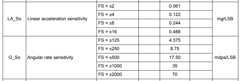
I had this problem a couple weeks ago. In section 4.1 of the LSM6DS3 datasheet there is a type column which gives you scaling constants depending on which mode you use. So if you want the correct acceleration you would read the raw acceleration and multiply by 0.061 assuming it’s in the ±2 mode (can be changed which register writes as well, check datasheet). Similarly, if you wanted to read the gyro, you would divide the raw value by 17.50

Here’s some example code:

void loop() {
setMotionInterrupt(IMU);
float accelX = (IMU.readRawAccelX() * 0.061);
float accelY = (IMU.readRawAccelY() * 0.061);
float accelZ = (IMU.readRawAccelZ() * 0.061);
float gyroX = IMU.readFloatGyroX() / 17.5;
float gyroY = IMU.readFloatGyroY() / 17.5;
float gyroZ = IMU.readFloatGyroZ() / 17.5;
}

I don’t remember what these writes do, but I call this in my loop before printing my saved accel and gyro vals. https://content.arduino.cc/assets/st_imu_lsm6ds3_datasheet.pdf

void setMotionInterrupt(LSM6DS3 & imu) {
imu.writeRegister(0x10, 0x60);
imu.writeRegister(0x58, 0x90);
imu.writeRegister(0x5C, 0x00);
imu.writeRegister(0x5B, 0xD);
imu.writeRegister(0x5E, 0x20);
}

You’ll also have to make sure your IMU object in instantiated the same.

LSM6DS3 IMU(I2C_MODE, 0x6A);

Notes from the Data Sheet… FYI 1LSb = 70 mdps at ±2000 dps full scale.

  1. Typical specifications are not guaranteed.
  2. Measurements are performed in a uniform temperature setup.
  3. Values after soldering.
  4. RND (rate noise density) mode is independent of the ODR and FS setting.
  5. Gyro noise RMS is independent of the ODR and FS setting.
  6. Noise density in HP mode is the same for all ODRs

Good Stuff,
HTH
GL :slight_smile: PJ
try this also. Does it give the proper orientation output?

Thanks for finding those! @PJ_Glasso

1 Like

@cam @PJ_Glasso Thanks both for answering

But im confused,
@PJ_Glasso When i adjust the code you sent (removing the display stuff) the orientations seem right.

@cam How do i know which mode im in? im using this library https://github.com/Seeed-Studio/Seeed_Arduino_LSM6DS3/blob/master/LSM6DS3.cpp

it seems to be already multiplying the ``typ``` constant. In your own code, do you multiply with the raw values of the gyro or with the readFloatGyro? as in the code you sent above, you dont multiply with the raw values.

Here is what i want to do again: I simply want to increment a counter everytime it rotates 180 degrees (3 counters for 3 directions)

If someone could help me with that : )

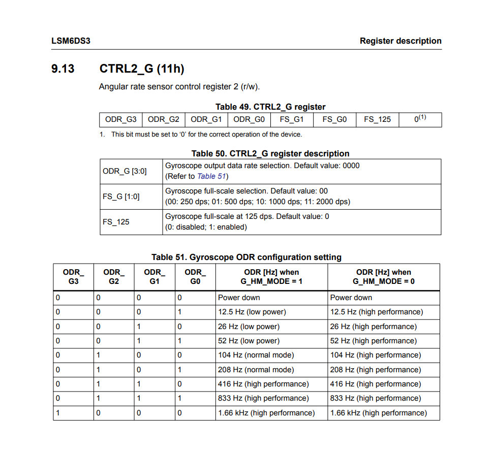
Registers 5 and 6 control the angular rate sensor, so for example if you wanted 1000 dps you would write out the following

imu.writeRegister(0x11, 0x8);

This means that you write to register 0x11 the hex data 0x8. The 0x11 comes from the datasheet screencap below and is right beside the title in the bold parenthesis (ignore the ‘h’). The 0x tells the compiler to read it as hex. That 0x8 might look a little confusing at first so we can break it down.

Since we want to change FS_G1 (position 5) and FS_G0 (position 6) we would write out the following data 00001000, the first four zeros are the default value, the next values denote the 1000 dps, the next is default value, and the final must be 0 (table 49). I then take 00001000 and put it in a binary to hex converter, which becomes 8 and then is written to the register.

Additionally, you can check below before you write to the register to see the default is 250 dps.

I mistakenly put readFloatGyro (oopsies!), but yes you’ll read the raw value and then divide it by the coefficient. I think the readFloatGyro attempts to check the register, to clean up the data, but it dividing the raw val does the job as well.

For your use case, reading when it rotates 180 degrees would mean you need create a new variable to sum up each new measurement. Gyros read in deg/s but you need deg.

A final consideration is using something like a complimentary filter to reduce gyro drift (since it’ll mess up your readings). ‘Phil’s Lab’ on youtube has a great video about complementary filters.

Let me know if you have any other questions!

Hi there,
Ok that’s good to hear.
You’ll need to read the data sheet and perhaps print out the GYRO config registers in your code and review the settings. After edit the settings to be pertinent to your application needs, BTW the Demo’s are just that , they don’t do anything super fancy Just shows the chip is working and that your code is NOT garbage. :slight_smile: The rest is up to :index_pointing_at_the_viewer:
I’m using the floats, here,

// Calculate gyro motion magnitude based on gyroscope data (you can adjust the threshold as needed)
  float gyroMotionMagnitude = sqrt(gyroX * gyroX + gyroY * gyroY + gyroZ * gyroZ);

For my application, This line of code calculates the magnitude (or length) of a three-dimensional vector using the formula for Euclidean distance. The vector components are gyroX, gyroY, and gyroZ.

Here’s a breakdown of the line:

  • gyroX, gyroY, and gyroZ are variables representing the components of a three-dimensional vector, likely obtained from a gyroscope sensor or a similar source.
  • gyroX * gyroX + gyroY * gyroY + gyroZ * gyroZ calculates the sum of the squares of each vector component.
  • sqrt(...) calculates the square root of the sum of squares, resulting in the magnitude of the three-dimensional vector.

So, gyroMotionMagnitude will contain the length of the vector represented by the gyroX, gyroY, and gyroZ components.
This is often used in applications where the overall motion or acceleration of a device in three-dimensional space needs to be measured or analyzed.

What you need to do is not that difficult,
what code do you have so far ? Post it up we can suggest edits.
HTH
GL :slight_smile: PJ :v:

Thanks @cam @PJ_Glasso

So, what ive got right now is just this.

#include <ArduinoBLE.h>
#include "LSM6DS3.h"
#include "Wire.h"

LSM6DS3 myIMU(I2C_MODE, 0x6A);

float x, y, z;
// Previous angle values
float angleX = 0, angleY = 0, angleZ = 0;

// Previous time in milliseconds
unsigned long previousTime = 0;


#define XBASE -0.02
#define YBASE -0.16
#define ZBASE -0.03

void setup() {
  Serial.begin(9600);
  // Initialize LSM6DS3
  if (myIMU.begin() != 0) {
    Serial.println("LSM6DS3 device error");
  } else {
    Serial.println("LSM6DS3 Device OK!");
  }
    // filter.begin(25);


Serial.print(0); // To freeze the lower limit 
Serial.print(" "); Serial.print(1000);

}

void loop() {

  float accelX = (myIMU.readRawAccelX() * 0.488);
  float accelY = (myIMU.readRawAccelY() * 0.488);
  float accelZ = (myIMU.readRawAccelZ() * 0.488);

  float gyroX = (myIMU.readRawGyroX() / 16.50);
  float gyroY = (myIMU.readRawGyroY() / 16.50);
  float gyroZ = (myIMU.readRawGyroZ() / 16.50);


 unsigned long currentTime = millis();
  float dt = (currentTime - previousTime) / 1000.0; // Delta time in seconds
  previousTime = currentTime; // Update previous time

  // Integrate gyro data to get angles
  angleX += gyroX * dt;
  angleY += gyroY * dt;
  angleZ += gyroZ * dt;

  // Print the angles
  Serial.print("Orientation: ");
   Serial.print(angleX);
   Serial.print(" ");
   Serial.print(angleY);
   Serial.print(" ");
   Serial.print(angleZ);
   Serial.println();
}


The reason for the 70 and 0.488 is that it seems that the library sets the FS to 16 and 2000.

This seems to give decent results (the angles seem right), however it does drift quite fast :confused: Anything i can do about that?

You can change these with register writes if you want

I think these might also be 17.50 instead of 16.50

Yeah the drift is pretty bad! But there are some ways to get around it. There are some filters that can be used that use sensor fusion (combination of data from multiple sensors) to lessen the error. The video below talks about a complimentary filter which combines data from the accel and data from the gyro to help negate the drift. There are some filters that are talked about in later videos, but the complementary one is a great place to start!

I haven’t implemented it into my work application yet, so I can’t provide much insight.

Additionally, you could add a ‘calibration’ section where you let the board run for maybe ~10 seconds or so to collect data and then average them together. You could then subtract your average from the measured values. Its a pretty rough approach, but it might be able to work depending on the length of time you want to measure data.

For example:

float realGyroX = calcGryoX - avgGyroX

1 Like