Hi,
I am working through the ‘getting started’ part of the WIO LTE Wiki.
Within Arduino IDE version 1.8.15 : Boards Manager:
When I attempt to install version 1.8.2 of the Seeed SamD Boards (in boards manager), the installer gives up an error which says :
> CRC Does not match, file is corrupted. It may be a temporary problem, please try again later.
When I install the earlier version 1.8.1 it works OK, without any error. This issue is not temporary, as I note another person has reported the same Issue yesterday.
Seems like the 1.8.2 version needs some work (a rebuild). Over to you guys.
I have confirmed that, with 1.8.1 installed, the board WIO LTE does not appear under SEEED SAMD Boards list. So this issue is definitely going to hold me up, as I will be unable to go ahead and run the examples etc to confirm my board is functioning properly.
As far as I can tell the Wio Tracker used the SAMD processor but the Wio LTE uses the STM32F4 processor. And if that is the case, I suspect that you will run into the same issues I have.
The installation instructions tell you to use these URLs for the board manager additional URL:
https://raw.githubusercontent.com/Seeed-Studio/Seeed_Platform/master/package_seeeduino_boards_index.json
404 error
https://files.seeedstudio.com/arduino/package_seeeduino_boards_index.json
Does not have the LTE board
https://raw.githubusercontent.com/Seeed-Studio/Seeed_Platform/master/package_legacy_seeeduino_boards_index.json
Appears to work
And then the next hurdle is getting the Arduino IDE to recognize the board. From Seeed the board will enumerate as a virtual COM port VID 0483 PID 5740, and if you open the serial monitor it shows that it is running Espruino firmware.
The Boot0 buttons puts the board into DFU mode as STM32 BOOTLOADER VID 0483 PID DF11
Then programming from the Arduino IDE I get errors
Invalid DFU suffix signature.
A valid DFU suffix will be required in a future dfu-util release!!!
can't detach
But it appears to work.
Wow.
I tried these steps out but looks like you just saved me a lot of delay and frustration.
But in Fact, I found that the required board definition was found on the following Link:
http://www.seeed.co.jp/package_SeeedJP_index.json
On this link is found explicit definitions for WIO LTE Cat 1 (and some others).
I found this link by clicking upon the link at the bottom of the ‘Additional Boards Manager URLS’ form; the link text ‘Click for a list of unofficial Boards Manager URL’s’
YOUR response, while not exactly correct in this case, led me to the conclusion that the Seeed Documentation might not be so accurate as one might desire. Note tactfulness (really the documentation is rubbish.) The documentation is also misleading when it comes to setting up the Com port for the board.
I really think that Seeed need to look at making the documentation more accurate. But I have no way to coax them to do so.
Cheers to you !
Thank you for your help. I can see the link in the dialog now - missed it because it just looked like text.
As pointed out in the wiki https://wiki.seeedstudio.com/Wio_LTE_Cat.1/ you cannot use the Arduino IDE’s serial monitor, but rather need to use a third party serial terminal. If you use the IDE serial then you need to open and close the IDE each time you switch between bootloader and virtual com port modes.
OK, just to make sure I got it right (at risk of trying your patience !).
What port mode (driver) needs to be active in order to be able to upload compiled code to the board using Arduino IDE ?
And, using the 3rd Party Monitor like ‘Serial Port Monitoring’, am I able to monitor debug output without switching modes ?
Uploading of code using Arduino IDE doesnt count as using the IDE Serial right ?
How do I switch between bootloader and virtual com port modes ?
I can add further to this.
Earlier, I compiled an example sketch and uploaded it. The sketch sends an SMS Message. When it runs, two red LEDs light up on the board nearby the battery connector (missing in my case).
But after that, the device “STM Microelectronics virtual Com port (comx) is no longer recognised, instead I get an error message when the USB is plugged in. Device manager lists the connection under Universal Bus Controllers as ‘Unknown’…”
I found the STM Microelectronics Virtual com port driver under “legacy devices” and installed it. The STM Microelectronics Virtual Port then appears (as faulty) under Ports as COM5.
I then find that ‘Serial Port Monitor’ is able to find that COM Port. But there is an error message (“Error opening Com Port”.) and the port is non functional.
Meanwhile, if I press on the Boot Button beneath the board and Plug in the USB at the same time, the port is recognized as STM32 Bootloader.
That’s fine as far as it goes, but Arduino IDE does not recognize either the COM5 port OR the bootloader. So Unable to publish code.
I think I first need to do a master reset on the Wio LTE Board and begin again.
I will research how to do that.
But I will need to learn how to switch modes without all this drama. I just want to verify that the board is functional, that the SIM works, that I can save files to the SD Card. Then I will be able to carry on and set up test programs to perform data transfers as planned for the project into which I need to integrate this device.
Basically I need to learn how to use it, but it looks like it is going to be problematic and tedious to program and debug.
This took me a while to sort out as well. At first I recommend using the Arduino IDE for the serial monitor - you just have to close and re-open the IDE. The reason is that not all serial monitors work with the virtual COM for some reason (Termite did not). SSCOM did work, but is not 100% in English.
Edit: The terminal program needs to assert DTR
Put the board into DFU mode by holding down the boot0 button then pressing and releasing the reset button. I have device manager open the whole time to see what is going on.
Then I can’t remember if I had to use Zadiag to change the USB driver, but currently in device manager I have STM32 BOOTLOADER VID 0483 PID DF11 and Zadiag shows it using the WinUSB driver.
To program the board I have to then close and re-open the Arduino IDE, which then shows the Port greyed out. But it will program using DFU, even though an error message is shown (the Wiki mentions this).
Then reset the board, close and re-open the Arduino IDE. Device manager shows STMicroelectronics Virtual COM Port (COMX) VID 0483 PID 5740. Zadiag shows WIO_LTE CDC in FS Mode using usbser (v1.4.0.0). The Arduino IDE shows a COM port and the serial monitor works, but you need to close and re-open the IDE after you reset the board.
OK, Many Thanks. Looks like I should be able to coax it to work using the steps you provided. I will try it tomorrow. I got tired of the thing today and gave it a rest…
Initially, I used Zadiag and it display more or less what was expected, and I was able to do as suggested in the notes. Subsequently, Zagiag does not display any COM Port details on the left side of the display, and nothing in the drop down.
The trick about : Arduino IDE, which then shows the Port greyed out. But it will program using DFU, even though an error message is shown
seems to be key as I had thought the compile/publish stage would not work if com port was not selected. I will give it a go, see where it leads !
I think the board designer has a lot to answer for. They could have selected a better USB chip that is much more compatible with Arduino. Other boards do not seem to have this problem.
My ancient 4 Y/O Windows 10 PC is part of my issue. Whilst you blithley say “you just have to close and re-open the IDE” for me that takes 5 minutes every time. I do wish that I had a Mac to do this on, but its looking I must wait until at least September before I can get my hands on a 16 inch Macbook Pro with M1x silicon. And, with a Mac, looks like this might have all just worked… I guess its one reason you pay so much for them.
Opening and closing the IDE takes about 5 seconds for me (3 year old laptop).
I have got both the Seeed Wio LTE Cat.1 from seeed.co.jp to work and also the WioTracker LTE package_legacy_seeeduino_boards_index.json to work. They install quite different package files. I think that there are problems with the jp version in that it was hanging upon the initialization of the WioTracker object.
I’m not sure that the WioTracker class is that good anyhow. I don’t like the way you can either use the GPS child or the Ethernet child but not both. And I can’t see how the command parser copes with unsolicited messages. Parsers like that work for simple examples using a lot of delays and timeouts but are not that good once you try to write a real application.
Be warned there are a couple of string quotes which did not translate from Chinese to the correct quote character ". If you switch on the compiler warnings you’ll see something about an unknown string constant.
As of this morning I opened up Arduino IDE and it informed me that there was an update to ‘Boards’; and I discovered Seeed have been busy.
Version 1.8.2 of the Seeed SAMD Board Manager now installs correctly.
The also deprecated a number of the other Seeed Board Manager entries.
That’s one issues now solved.
It leaves me with the remaining issue.
By Default, when the WIO LTE device is plugged in, Windows finds the STM32 Virtual Com Port device and it becomes visible under PORTS and COM in Device Manager. At some stage I deleted this, thinking it was incorrect, or thinking it had malfunctioned. Now I know that it is likely correct.
However, when I now plug in the device, It Appears under ‘Universal Serial Bus Controllers’ as and ‘Unknown Device [Device Descriptor Request Failed]’
What I think this means is that my earlier playing around deleted it from USB.inf or USB.inf_loc (or similar).
I have tried installing the STM32 Virtual Com POrt Drivers from the STM Website. But they are for Windows 7 and 8. I tried 64 bit versions of those, and I tried installing them via the ‘Legacy’ installer option in Device Manager.
This causes static entries to appear under Ports and COM in Device Manager, but a yellow ampersand indicates the driver is not functioning.
I am presently trying to find out how to restore the original Microsoft version of USB.inf
Unless the USB Device acquires a COM appearance in Device Manager, then I am unable to use the 3rd party ‘Serial Port Monitor’ or REAL Term to monitor debugging output. Whilst you have kindly provided info on how to switch between DFU Mode and COM Mode; the latter is not working.
I can publish code, but not debug it, or even learn if the code is working…
I am running google HOT on trying to find out the answer, if you have further suggestion please let me know.
Cheers
Normally windows update will find the right driver. On one PC the wio identified as the DFU for some other hardware device I had, so I had to manually update the driver.
ST virtual COM driver
I’m at the programming part … and nothing works very well. It will work for a while and then the wio will fail to enumerate USB, which is frustrating because then there is no COM for debug output. Then if I disable Peripherial_Init(); in WioTracker::WioTracker it works.
I found the error in the library:
C:\Users\xxx\Documents\Arduino\libraries\Wio_LTE_Arduino\gnss.cpp: In member function 'bool GNSS::enable_NMEA_mode()':
C:\Users\xxx\Documents\Arduino\libraries\Wio_LTE_Arduino\gnss.cpp:154:25: warning: unknown escape sequence: '\342'
     if (!check_with_cmd("AT+QGPSCFG=\“nmeasrc\",1\r\n", "OK", CMD, DEFAULT_TIMEOUT, 2000)) {
Note that the quote “ is not the same as a actual quote ".
Update: I got it to work. The JP platform does not work; the ‘WIO Tracker LTE’ does work. And I had the SIM upside down in the connector.
I followed a different path because my symptoms are different.
I reached out to ST’s technical support. Here is their response verbatim:
Subject: Drivers for STM32 device
Status: Solution Proposed
Description: Hi Bryn, On Win10, windows native driver is introduced for USB CDC driver. ST does not provide the CDC class driver for WIN10. Here is an article from Microsoft about USB CDC driver. https://docs.microsoft.com/en-us/windows-hardware/drivers/usbcon/usb-driver-installation-based-on-compatible-ids To connect to host PC, the firmware on MCU has to support USB CDC device. This is an open question if MCU firmware support USB CDC. I would suggest you to contact your vendor for technical support. ST is not the right window for customized firmware support. Regards, Bossen WU
=========
The response is predictable, but if you follow the link it yields interesting and educational information on just how this aspect of Windows plug’n Play works.
In my own case the recognition of the STM Virtual Com port support vanished after I uploaded my first sketch. So I am wondering more about how that happened. The sketch is firstly a copy of the very first example (sending an SMS). After uploading, two red leds turned on, one flashing.
The sketch does not actually work, no sms is sent. So now I am looking at your observation that you had the SIM inserted incorrectly. Please tell me which way up worked for you. My sim is inserted with gold contacts side downward, the bevelled edge of the sim is on the left.
I found a photograph of SIM Inserting on the Wiki for Wio Tracker,. Its a different board, the dual purpose card slot is in a different board position, but the SIM orientation is same as mine.
Thanks
Bryn
Sim goes in with contacts down (towards PCB).
With the virtual COM driver normally you just delete the driver and allow windows to find the WHQ driver. You may have to show hidden devices first or see if it is listed as unknown.
For testing I would start with the RSSI example. Add some code to the uart module so that you can see what is going on. I added some to send_cmd (both functions) and wait_for_resp. You should see the result of the +CPIN? as READY which shows the SIM is ok.
Thanks for your response.
I may need to delete the DFU driver in order to get back the default driver for virtual Com port. Today, when switching from DFU mode to VCP mode, the VCP driver is not found. I have not seen any control within Device Manager that provides capability to hide or show inactive or disabled devices. I will search for one now you indicate it may exist.
My current working hypothesis is that my uploading of example sketch has somehow changed the USB signature of the device. The lack of a battery due to broken connector may also be involved.
My diagnosis will be helped when on Monday my replacement Wio lte device from Mouser gets delivered. I will discover then if the problem of incompatible battery connectors is common among the mouser-held stock manufactured on 04/30/2020 or is just a single instance.
I will also be able to discover if the symptom of unrecognised VCP noted earlier carries through to the second instance or not.
If not carried over (that is, if the device is now recognised by windows) this would indicate that the sketch has altered the COM port signature of the device.
I do not understand the terms used in your second paragraph. I will study some more to see if I can make some sense of it. I think it is referring to the writing of a further sketch to perform the actions you describe. It’s beyond me at the moment.
As further investigations continue:
-
I found “show hidden devices “ under “view” menu item In DM.
When I selected it, the ‘STMicroelectronics Virtual COM port (COM4)’ becomes visible in Ports (COM & LPT) .
I note that the driver is usbser.sys dated …08/2013
I updated it, and nothing changed.
-
I plugged in the Wio LTE device. Symptoms same as before, it’s an ‘Unknown USB Device…’
It appears to have heard the signature “USB\VID_0000&PID_0002……
Which is not what it needs to be to match the STM VCP, which is VID_0483&PID_5740\0000…01A
-
I uninstalled the DFU device ‘STM32 Bootloader’
This appeared to have no effect on the symptoms noted earlier.
This reinforces my earlier hypothesis that it’s the device signature that has changed, likely as a result of the sketch I installed.
I am now wondering if it’s possible somehow to return the device to its original factory setup. Oh wait… I already got that one in hand, I ordered a new one. 
Hi @Bryn_Parrott ,
Did you use SeeedJP STM32 Boards on Wio LTE Cat.1 board?
If yes, I can help you.
FYI
Make a development-envirionment for Wio LTE Cat.1.
https://seeedjp.github.io/Wiki/Wio_LTE_for_Arduino/Setup-ja
(Sorry, it is Japanese only.)
Thank you @matsujirushi for responding.
The link that you provided looks like it might help but for me, I will need to read it in English. Is there an English version available ? Sometimes automatic translation makes a mess of the meaning. An expert in two languages would need to make corrections.
I now have my 2nd Wio LTE board, and it has the same problem with battery connector as the first, that is the battery plug will not fit the battery socket despite similar size. Only Seeed can fix this problem, buttthey have not yet acknowledged culpability.
Secondly providing the capability to debug using a com port monitor app and simultaneously have file upload capability (DFU) to load firmware in context of learning and debugging proposed coding solutions.
Thirdly undocumented 3 buttons on the board have functions of boot, reset and xx (unknown) and I think your document addresses that concern, to provide an explanation of how the buttons should be used.
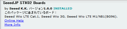
The original issue of Arduino Boards manager for Wio LTE has been addressed by Seeed support who fixed the issue on Git download, including deprecating of the JP version of the board manager.
So as far as I know I am using 1.8.2 Of the Seeed boards manager not the Seeed JP boards manager.
I am wondering if the issue of very poor English language documentation for Wio LTE is caused by them failing to fully translate all of the Japanese documentation. Only some if it. Then failing to mention that original documents are available in Japanese language. Could it be true ?
I am in process to address the issue of virtual com port driver failing after a sketch has been uploaded. I have ordered a 3rd part USB to UART dongle device from Amazon. Intend to connect it to the Grove UART port. It’s annoying Seeed did not include a JTAG pin field on the board. Every other Arduino board has one…
The 3rd party dongle will utilise another com port driver and consistently retain the same USB signature. It will need to be supported by code of course, but is fairly trivial few lines to add defining uart as debug output port.
Thanks and cheers
Bryn
Actually, I check the link again.
The 2nd time I opened the page Google Chrome offered to translate it for me.
I found that the translated version gives an EXCELLENT well written dissertation of how to get started with this board. And it translates very well, and aids understanding.
Furthermore, there are links to another “reference manual” document, which is another one Seeed failed to provide in English on the wiki. Unfortunately, because this one contains a mix of both Western and Japanese characters, it’s not offered to translate, but it’s essential for someone to go beyond basic example sketch programming.
Again we see a failure by Seeed to provide a resource to speakers of English customers.
Are Seeed Just lazy, incompetent or are they racist, Chinese supremacy?
I think they are just lazy.
The Seeed product manager will get a huge kick in gluteus maximus (Latin, medical) from me if I ever get to talk to him. I may used a raised voice too.
I tried without success to find a local supplier of the batteries and/or connectors. Still looking….
It’s not made any easier by the fact the connectors are not one of the usual suspects…. JST or Molex , they are some Brand X from China nobody ever heard of.