Hello everyone.
I want to drive high current dc motors (Coreless motors) with (XIAO ESP32C3 Board).
But when motors on, voltage drop between 0.5~0.7v.
This happen causes battery voltage 3.7v reduce to 2.8~3.0v and the board RESET!!!
I think this happens because the regulator voltage cannot be activated.
Now I want to know how to reduce the voltage drop and fix this problem from resetting the board when the battery voltage is between 3.3~3.7V?
Hi there,
Have you tried a more powerful battery? why no motor driver?
GL  PJ
PJ
Hey, are you using some sort of motor driver board? How are you powering everything? A circuit diagram would be very helpful to try to diagnose the issue.
Hi.
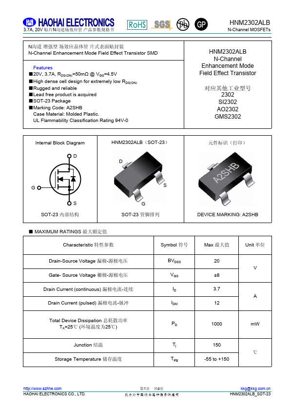
I’m using A2SHB MOSFET to drive coreless motors, and 500mAh 1S LiPo battery (25C) to power up.
Voltage drop is normal when the motors are working, because each motor draws 0.5 to 1.5 amps.
Now my question is how can I fix the voltage drop problem for the board so it won’t reset?
Everything is fine before the battery voltage reaches 3.7, but after that the board resets for the reason I said.
Hi.
I’m using A2SHB MOSFET to drive coreless motors, and 500mAh 1S LiPo battery (25C) to power up.
Voltage drop is normal when the motors are working, because each motor draws 0.5 to 1.5 amps.
Now my question is how can I fix the voltage drop problem for the board so it won’t reset?
Everything is fine before the battery voltage reaches 3.7, but after that the board resets for the reason I said.
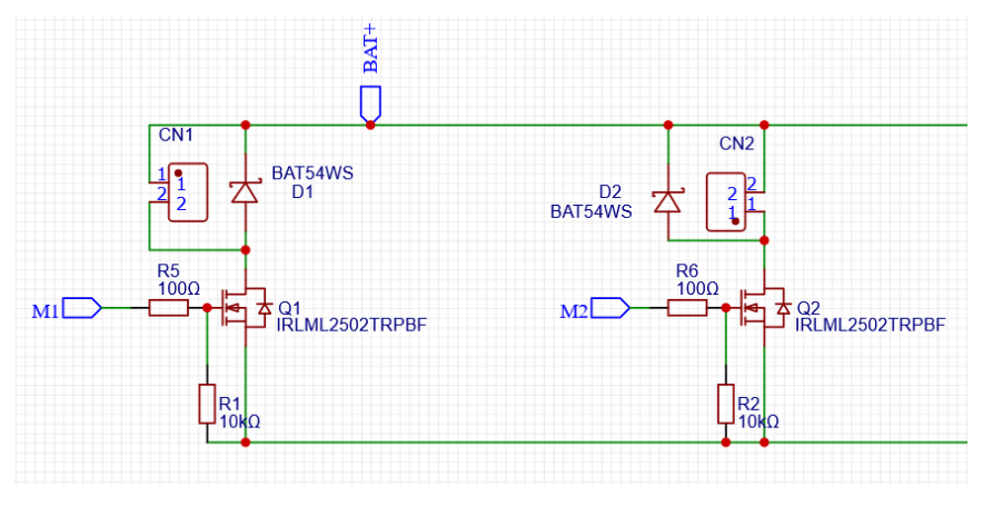
(The circuit schematic is similar to the picture below)
that battery will not power a motor very long, also be careful not to overdischarge the lipo and damage it…
Hi, thanks for reply.
The general consensus among the RC modeling continuum is that LiPo batteries should not be discharged more than 3 volts per cell.
I want to use more power from the battery until the voltage reaches 3.3V. Because according to the datasheet, it is said that up to this level does not cause a problem for the battery and it should not be less than 3 volts.
the brownout of the chip is just showing you that you are using more power than the cell can provide, if we tell you how to prevent this you will just use more power and damage your cell… so this is why we are telling you use a bigger cell… or test with a bench power supply first
I did the same project with an esp8266 board with no problems and no cell damage.
Because the esp8266 board needs at least 2.5V~3.6V to activate, while the esp32c3 board needs at least 3.3V.
The project is to build a tiny quadcopter, so a bigger battery cannot be used.
Now my question is how can I fix the voltage drop problem for the board so it won’t reset?
Everything is fine before the battery voltage reaches 3.8, but after that the board resets for the reason I said.
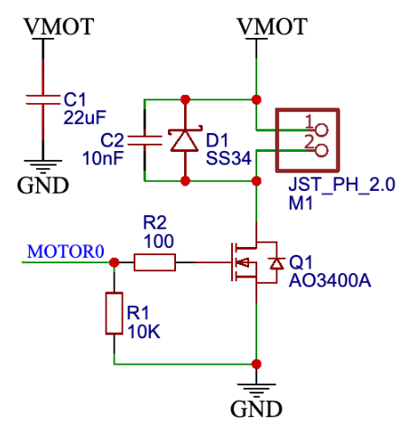
I’m not seeing any capacitors on your diagram there, the other replies are also right about switching to something like a 2S battery but you should really throw some capacitors on there to deal with the high starting current draw of the motors
Thank you 
I’m a noob in electronics
Can you explain more about it?
What capacitor is suitable to solve the problem?
Is 10nF ok?
this schematic is correct?
in the future please be more specific, you are building a quadcopter with one motor and no motor driver?.. I dont see that project getting off the ground…
Hi Ali_Karimi_Zadeh1,
I have made some small quadcopters too. For reference!
ESP8266 requires a minimum operating voltage of 2.5V while ESP32C3 requires 3.0V. This is probably the reason why the ESP32C3 resets at startup, while it worked fine with the ESP8266.
See the following table in the datasheet.
ESP32C3 Table 12: Recommended Operating Conditions
ESP8266 Table 5-1: Electrical Characteristics
Although some experimentation is required, my feeling is that a capacitor of 100uF or more is necessary.
Hi there,
I would concur at a minimum 100uf to 220uf would be the range I would try.
Start out at 220uf and work your way down, When it resets add half.
Your close , you’ll get it. Go look at the motor notes, data sheet and the Driver boards that are available. See what values they are using having tuned it to the motors in the appnotes.
HTH
GL PJ

Hi msfujino,
Thank you for reply.
This schematic and connection of capacitor C1, C2 its true?!
I think we can solve (Voltage Drop) with MT3608 voltage booster…
It seems to be a suitable and efficient option 
It is a good solution if a step-up converter can be used, although it requires more components.