I am a mechanical engineer with no knowledge of electronics, Arduino or registers etc. I have
Seed studio xiao nrf52840 sense. I want to convert gyro and accelerometer values correctly to angles(degrees or radians). Once I am confident that thses values are correct I will implement a 1D kalman filter to combine those 2. I am struggling with first step itself.
I read gyro and accelerometer data.
I took some reading to get average zero and subtracted them from sensor value in order to calibrate the sensor.
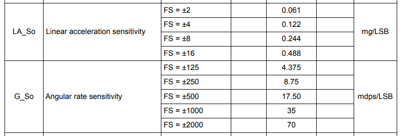
I tried different factors from this table in image. Such as 8.75, 17.5 ,70
and welcome here, Since there is only a little data on this but lots of info… I thought let’s ask.
I have experimented also with the AWT in the Xiao and this basically sums it up in a small thesis.
HTH
GL PJ & Al
When capturing raw accelerometer and gyroscope data (e.g., from the LSM6DS3 on the Xiao nRF52840 Sense) and you want a meaningful orientation estimate or cleaner motion data, you typically need some form of sensor fusion or filtering. The exact approach depends on your project requirements. Here’s an overview:
1. Basic Filtering (Noise Reduction Only)
Low-pass filter: Smooth out high-frequency noise in your accelerometer data (e.g., to stabilize readings in a static orientation).
High-pass filter: Remove low-frequency drift in your gyro signals or gravitational component from the accelerometer data.
Implementation: You can do this manually by applying a one-pole filter or by using built-in LSM6DS3 digital filters. Some libraries let you configure these filters directly in the sensor.
2. Complementary Filter (Simple Sensor Fusion)
If you just want a rough orientation estimate (pitch/roll/yaw) without the complexity of a full AHRS, a complementary filter often suffices:
Accelerometer for low-frequency orientation info (gravity vector).
Gyroscope for high-frequency changes (fast rotations).
Implementation:
cpp
Copy code
// Pseudocode for roll/pitch with complementary filter
// alpha ~ 0.98 for example
pitch = alpha * (pitch + gyroPitchRate * dt) + (1 - alpha) * accelPitch;
roll  = alpha * (roll  + gyroRollRate  * dt) + (1 - alpha) * accelRoll;
This approach is easy to implement and typically good enough for hobby robotics or stable platforms.
3. AHRS Libraries (Madgwick, Mahony, Kalman)
For more robust 3D orientation, heading, or advanced motion tracking, you can use an Attitude and Heading Reference System (AHRS). These algorithms fuse accelerometer, gyroscope, and optionally magnetometer data into a stable orientation (often a quaternion or Euler angles):
Madgwick filter: Good for low-resource MCUs, offers fast convergence.
Mahony filter: Similar to Madgwick, also widely used in embedded AHRS solutions.
Kalman filter (or Extended/Unscented Kalman Filter): Very powerful, but more CPU/memory intensive, typically used in professional IMU solutions.
For more advanced usage, you can implement your own Extended Kalman Filter on the nRF52840 if you have enough flash/RAM.
4. Built-in LSM6DS3 Features
The LSM6DS3 includes:
On-board FIFO: You can batch up accelerometer/gyro samples.
Embedded pedometer, step detection: If you need step counting or basic motion detection.
Some digital filtering: You can configure its internal low-pass or high-pass filters.
If you only need simpler tasks like motion detection or step counting, you might leverage these built-in features without writing your own filter.
Which Do You Need?
Just smoothing noise? Use built-in LSM6DS3 filters or a simple low-pass approach.
Want to track pitch/roll or basic orientation? A complementary filter is often enough.
Full 3D orientation or stable heading? Use Madgwick/Mahony (for minimal code) or a Kalman filter (for more accuracy and complexity).
Example: Using Madgwick Filter
Include a Madgwick library in your Arduino code.
Collect accelerometer (ax, ay, az) and gyroscope (gx, gy, gz) data in loop().
Feed those into the Madgwick update function:
cpp
Copy code
float ax, ay, az;  // from LSM6DS3
float gx, gy, gz;  // from LSM6DS3
float dt = 0.01;   // or measure actual loop time

Madgwick.updateIMU(gx, gy, gz, ax, ay, az, dt);
// Now get the orientation from Madgwick: quaternion, or euler angles
float roll  = Madgwick.getRoll();
float pitch = Madgwick.getPitch();
float yaw   = Madgwick.getYaw();
Use roll/pitch/yaw for your application (robot balancing, drone, orientation display, etc.).
Summary
No single “one-size-fits-all filter.” It depends on your performance needs and complexity tolerance.
For quick & easy orientation: complementary filter. (with AWT it’s a great solution)
For more accurate orientation: Madgwick/Mahony.
For high-end sensor fusion: Extended Kalman Filter.
You’ll likely pick one of these approaches to process your Xiao nRF52840 Sense’s accelerometer & gyro data effectively.
SO you know there are Calibration data from the factory in register locations , consult the Datasheet.
Read your values and apply them to your calibration data.
GL PJ
Also there is no Magnetometer so Drift is present and needs to be compensated for or rechecked and zeroed to be HARD core!
Also, its there a way to know Full Scale of gyro and accelerometer or change it?
I want to convert gyro deg/sec readings to degree. So I need to know the full scale of it.
Yea, the IMU is Great!, check out the Demo’s with code I have on here.
The Registers marked as Reserved must not be changed. Writing to those registers may cause permanent damage to the device. (note from data sheet) ONLY do READ’s of registers your not sure about!
The content of the registers that are loaded at boot should not be changed. They contain the factory calibration values. (it’s on another datasheet) Their content is automatically restored when the device is powered up It. The Gyro can be turned on and Off BTW also…
There is another more advanced datasheet for the IMU, that has them listed, also there exists a YT video of the drift and how to compensate for it… There might be a reference to both in a thread on here, YMMV
HTH
GL PJ
check out the PARK IMU code demo on here It will show you the register read and write methods.
No there is no Magnetometer , But NO incorrect… I won’t spoil the journey aside to say there is AWT if you snatch the pebble from the hand you will then learn the secrets of the IMU. Words like Filter, Kalman, Madgwick…
Here is your AI bone!
When calculating angles using an IMU (Inertial Measurement Unit), the most common filters used are Complementary Filters and Kalman Filters; with variations like the Madgwick filter and Mahony filter often employed within the complementary filter category, which leverage the combined data from the accelerometer and gyroscope to achieve accurate angle estimations while mitigating drift issues from the gyroscope alone
HTH
GL PJ
FWIW there are several threads on the subject with code examples and solutions.
SO is that a statement or Question,This isn’t the complaint department or an opinion Poll either… BTW, As it doesn’t belong in this thread, We try to be orderly and Helpful here , So Now You Know !
HTH
GL PJ
FWIW , Look up the meaning of “XIAO” maybe you get it
LOL, we get that a lot… So yes timing is one important thing , as alway Interrupt routines need to short as possible and ditch a bunch of print statements too, use the RGB LED to show status.
The FIFO is the single most useful tool on the IMU, Using it properly can yield the Highest speed of acquisition and very responsive feedback models. Check the demo’s on it forsure.
the AWT is another very useful mode, JUST like a phone knows its orientation in 3d space.
The filters are also a BIG part of the heavy lifting though, proper selection for the application is essential to get clean and Highly accurate data.
Read the TWO data sheets on it, look at the registers to get a handle on what you can read and write. The MOST important item however is the configuration registers (get to know those)
it’s NOT rocket science but it can be used for rockets … SO
HTH
GL PJ