Rainbowcube kit problem.

Hi all,

I recently bought a replacement kit to build (I dropped something on my first pre-built kit and broke it :cry: ) and I have built it and had some issues with it. Boy, that is a lot of solder connections to make.

Anyway, I have been able to debug all of my problems (and fix them :smiley: ) but 2 and I was wondering if I posted a picture, some code, and a description if someone might be able to help me figure out what is wrong. I have looked at the Eagle files of the circuit boards, traced paths with an ohm meter, and can’t for the life of me figure out what is going on. I wish I had one of the 8*8 led matrix’s to plug into my rainbowduino to test it, but I don’t. I am wondering if the problem could be there.

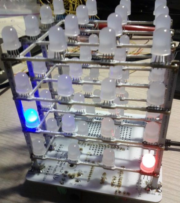
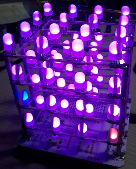
Briefly, I have 2 led’s that don’t light correctly. Green works on both of them. One of them will not light red, and the other won’t light blue. The led’s are mounted in the correct orientation. I also replaced one of them and still no go and the one I took out lights fine all 3 colors on my bench. My logic (and ohm meter) tells me that all of the traces are good because other led’s that connect to the same pins are lighting, and the common traces are good because they light other colors on these 2 led’s.

So should I post a picture, which xyz coordinates they are, my code, or what.

Thanks in advance for your help, John.

So now that I am home I thought I would post additional information. I hope it will help lead to an answer to my problem.

Thanks again, John.

1 the red led is at 0,0,0 and the blue one is at 1,3,0.

2 I attached 2 photos to show it.

3 Here is the code I was using for the photos:
This one just lights the 2 bad led’s purple.

#include <Rainbowduino.h>

void setup()
{
Rb.init(); //initialize Rainbowduino driver
}

unsigned int z,x,y;

void loop()
{
Rb.setPixelZXY(0,0,0,0xFF00FF);
Rb.setPixelZXY(1,3,0,0xFF00FF);

}

This code lights the entire cube purple

#include <Rainbowduino.h>

void setup()
{
Rb.init(); //initialize Rainbowduino driver
}

unsigned int z,x,y;

void loop()
{
for(z=4;z>0;z–)
{
for(x=0;x<4;x++)
{
Rb.setPixelZXY(z-1,x,0,0xFF00FF); //uses 24bit RGB color Code
delay (25);
//Rb.blankDisplay();
}
for(y=1;y<4;y++)
{
Rb.setPixelZXY(z-1,3,y,0xFF00FF); //uses 24bit RGB color Code
delay (25);
//Rb.blankDisplay();
}
for(x=3;x>0;x–)
{
Rb.setPixelZXY(z-1,x-1,3,0xFF00FF); //uses 24bit RGB color Code
delay (25);
//Rb.blankDisplay();
}
for(y=3;y>1;y–)
{
Rb.setPixelZXY(z-1,0,y-1,0xFF00FF); //uses 24bit RGB color Code
delay (25);
//Rb.blankDisplay();
}
}
for(z=0;z<4;z++)
{
Rb.setPixelZXY(z,1,1,0xFF00FF); //uses 24bit RGB color Code
delay (25);
Rb.setPixelZXY(z,2,1,0xFF00FF); //uses 24bit RGB color Code
delay (25);
Rb.setPixelZXY(z,2,2,0xFF00FF); //uses 24bit RGB color Code
delay (25);
Rb.setPixelZXY(z,1,2,0xFF00FF); //uses 24bit RGB color Code
delay (25);
}
}
cube 2.jpg
cube 1.jpg

I fixed it myself! Good old continuity tester and perseverance.

Briefly, I did a lot of poking and prodding the circuit, traced paths, confirmed it wasn’t my Rainbowduino or the LED’s. I found the pins on the 'cube that feed the LED’s with the problems and it turns out that the colors that were not lighting were shorted to ground. I went so far as de-soldering the cube from the main cube circuit board, confirming the shorts weren’t there, then I de-soldered the nearest riser to each LED and then I was able to isolate the shorts.

The 1,3,0 LED must have had a microscopic short at the LED because I couldn’t eliminate the short until I removed the LED and removed all of the solder from the pads where it was. It was not the LED, that tested good. I had been looking at the LED the whole time for a short and I never saw it.

The 0,0,0 LED I went through the same process but the short was on the riser. The short was under the jumper that needed to be on the riser. I had used a piece of de-solder wick for the jumper because I could not get it to just bridge the gap with solder for some reason. The jumper was actually shorted to the other line on the riser. I must have scratched it when I was soldering the jumper on.

After putting everything back together I am happy to report that I have a fully functional cube again! All I can say is I blame myself for poor soldering skills, not using the right tools for the job, etc… Be very careful when building projects and you will have success.

I hope my trials can help someone in the future.

I want to thank Seeedstudio for making the schematics and the images of the circuit boards available on the wiki. Without them I would have never gotten this thing fixed.

Now on to the programming! I am going to make it a clock for starters. I don’t know what else after that. I have a lot to learn and I will probably have to connect it to another Arduino via I2C (or xbee is my ultimate goal) to control it because I don’t think there are any available pins on the Rainbowduino.

Good luck all, John.