Questions about the Seeeduino XIAO Expansion board

I’ve just receive the Seeeduino XIAO Expansion board and rushed to explore it.

Congratulations for the excellent introductory wiki!

Schematics

However, I haven’t found the schematics. Where can I find them, if they are available?

Second pad

The buzzer section details one pad to solder.

However, the board I have has a second pad between the SD-card slot and the coin-cell battery holder. what is the use of this section pad?

SD-card example

Finally, is there an example to explore the SD-card?

Thank you!

1 Like

One more question!

No problem to debug using the Segger J-Link Edu programmer-debugger. Everything works fine thanks to the pogo-pins and the connectors.

Power provided by the debugger

The Segger J-Link Edu programmer-debugger has a 5V output to power the board. Using the +5V pin on the servo line doesn’t power the Xiao.

However, using the USB5V pin close to the Xiao works fine.

My guess is, the answer comes from the schematics!

1 Like

It appears the schematics have been added to the Wiki page under the Resources section.

It appears the LED control by User Button is rather misleading as the LED is driven in inverted logic:

  • LOW turns the LED on
  • HIGH turns the LED off

The best way to understand is to refer to the corresponding schematics, here for the Xiao LEDs and the Expansion Board PUSH1 push-button.

Here the updated example with more explanations.

const int buttonPin = 1;     // the number of the pushbutton pin
uint8_t buttonState = 0;    // variable for reading the pushbutton status
uint8_t oldState = 0;         // variable for previous reading

void setup() 
{
  Serial.begin(9600);
  while (!Serial);
  Serial.println("=== " __FILE__);

  // initialize the LED pin as an output:
  pinMode(LED_BUILTIN, OUTPUT);
  // initialize the pushbutton pin as an input:
  pinMode(buttonPin, INPUT_PULLUP); // push button released= HIGH
}

void loop() 
{
  // read the state of the pushbutton value:
  buttonState = digitalRead(buttonPin); // inverted logic

  // check if the pushbutton is pressed. If it is, the buttonState is LOW:
  if (buttonState != oldState) 
  {
    Serial.print(millis());
    Serial.print(":\t");
    if (buttonState == LOW) 
    {
      // turn LED on:
      Serial.println("Button pressed");
      digitalWrite(LED_BUILTIN, LOW); // inverted logic
    } 
    else 
    {
      // turn LED off:
      Serial.println("Button released");
      digitalWrite(LED_BUILTIN, HIGH); // inverted logic
    }
    oldState = buttonState;
  }
}

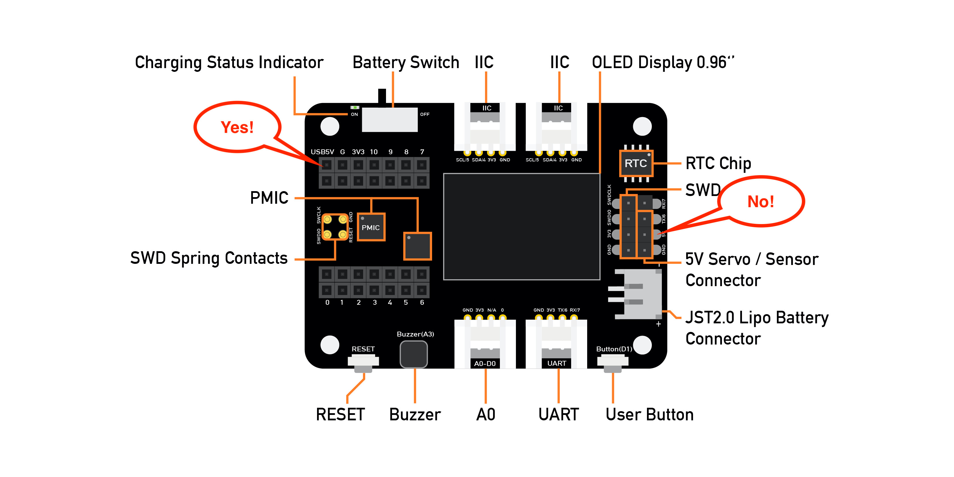
I am curious if anyone else is having a problem powering the expansion board and Xiao with just the lipo? I the expansion board setup and working fine with USB and it continues to work on the lipo after unplugging the USB. WIth unit running on battery, once it is shut off with the power switch it will not turn on by the switch until I plug in the USB.

Is there a while(!Serial) line in the setup() in your sketch?
If so, it will not start until you connect it to USB Serial monitor.

1 Like