Hey guys,
I’ve run into an issue that you might be able to help me with.
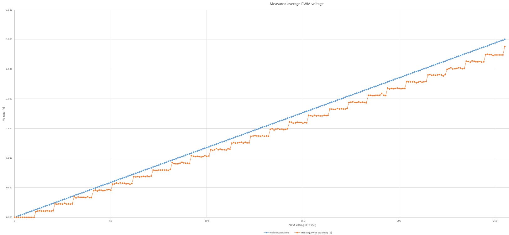
I’m using the Grove - I2C Motor Driver (TB6612FNG) board to stear a DC Motor. I want to measure the minimum voltage that my system still runs fine. For that I alter the PWM with values from 0 to 255 and check if the system still runs. Now I run into the issue, that the output PWM is not behaving linear with setting the values from 0 to 255. Instead it only changes every 10-12 values like a stair, see graphic below where I have the PWM setting on the x-axis (0 to 255) and the output voltage on the y-axis. The blue curve is the linear behaviour I expected and the orange curve is the actual output. Is there a way to achieve a more linear behaviour?
Hello Andreas,
We have noticed your problem and test it immediately.
It seems that the MCU on board couldn’t generate linear change duty PWM signal cause the problem.
Re-programming the MCU on board may help, but we could not offer further support since it has been discontinued.
If you want a more precise control on motor, you can consider using stepper motor instead.
Hey Liu,
Thanks for the reply. Unfortunately the DC motor is fixed so I cannot change it to a different DC or stepper motor. Is there a different board that has a more linear behaviour?
I need small steps in the range of 1.20V to 1.50V and with this board I can only set it to 1.26V, 1.37V and 1.48V. If the full 255 steps instead of the 25 currently were available it would work fine.
Thx and have a nice day, Andreas
There is a lot of choices!
If you want continue to use Grove IIC interface, you can try Grove - I2C Mini Motor Driver
If you are using Arduino, you can try Motor Shield V2.0 for Arduino
If you want to use PWM to driect control on your own, try MAKER DRIVE - MIX1508 H-Bridge Motor Driver
The Grove -I2C Mini Motor Driver is probably not suitable because we have a stall current of around 250mA and on the wiki it sais “Default maximum drive current 200 mA”. Is there no normal size version available?
Also: Concerning setting I2C addresses on the TB6612FNG, the specified address range (0x01 ~ 0x7f) seems to be incorrect. I was able to set the address to following ones:
0x01 doesn’t work
0x02 doesn’t work
0x03 works
0x04 works
0x05 works
0x06 doesn’t work
0x07 works
0x08 doesn’t work
0x09 works
Didn’t test higher ones, needed 5 different ones. Would be nice to add this to the specification, otherwise you think you’re doing sth wrong setting the address when it doesn’t work