Hi, I’m new here and a complete beginner. I’ve been trying for days, also with the help of AI, to control a motor for a model railway, but I just can’t get it right. The aim is to get a locomotive (15V) to oscillate back and forth on a track. The motor is a coreless motor and needs a PWM frequency of 32kHz. Slow acceleration and deceleration are also important. The maximum speed should be around 33% of vMax. What I have is a XIAO SAMD21, an Adafruit H bridge DRV8871. Wiring 15 volts to Xiao Power IN, D1 > IN2, D2 > IN1, all GND connected to each other, Motor +/- > Motor. No matter what code I try, my locomotive only travels backwards and at full speed. For some reason PWR is not taken into account, and neither is the change of direction. For me as a beginner, this is not solvable. But I can only say that the wiring isn’t wrong. I tested everything without PWM and it works. Does anyone have an example code that I could use as a guide?
Hello Welcome!
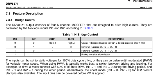
can you say what this means?
the driver and motor you described is a dc motor driver, so the motor does not need pwm… the power and speed is regulated by voltage and power applied to the motor
The example source code is here
I would recomend placing Int1 on pin 1 and int 2 on pin 2
are you using Arduino IDE with Seeed Studio unit selected?
I am assuming you are not, and therefore you are defining the incorrect pins in the code… because Physical Pin 1&2 on the XIAO is not necessarily the GPIO pin of the chip
https://files.seeedstudio.com/wiki/Seeeduino-XIAO/res/XIAO-SAMD21-pinout_sheet.xlsx
Sorry, I’m totally confused now. The applied voltage is a constant 15V. I want to use PWM to regulate this 15V so that the coreless motor (the locomotive) runs slowly, brakes to a stop, and then slowly starts again. What I meant by the sentence I mentioned is that the coreless motor runs at full load in both directions if I adjust the code so that it doesn’t use PWM. Once I implement PWM in the code, it no longer works.
This Code works but without PWM!
#include <Arduino.h>

// --- Pin-Definitionen ---
const int MOTOR_IN1_PIN = D2;  // XIAO Pin D2 verbunden mit IN1 des DRV8871
const int MOTOR_IN2_PIN = D1;  // XIAO Pin D1 verbunden mit IN2 des DRV8871

const unsigned long PHASE_DURATION_MS = 5000; // 5 Sekunden pro Phase

// --- Haupt-Setup-Funktion ---
void setup() {
  Serial.begin(115200);
  delay(100);
  Serial.println("--- Starte DRV8871 DIRECT HIGH/LOW TEST ---");
  Serial.println("Dies testet die 4 Grundzustaende des DRV8871 mit festen HIGH/LOW Signalen.");
  Serial.println("Keine PWM in diesem Test, Motor faehrt mit Vollgas.");
  Serial.println("Pruefen Sie das Motorverhalten und die Ausgaben am Seriellen Monitor.");

  pinMode(MOTOR_IN1_PIN, OUTPUT);
  pinMode(MOTOR_IN2_PIN, OUTPUT);

  // Initialer Zustand: Beide LOW (Freilauf), Motor sollte sich nicht bewegen
  digitalWrite(MOTOR_IN1_PIN, LOW);
  digitalWrite(MOTOR_IN2_PIN, LOW);
  Serial.println("Initialisierung: IN1=LOW, IN2=LOW (Freilauf)");
  delay(2000); // Kurze Wartezeit vor dem ersten Test
}

// --- Haupt-Loop-Funktion ---
void loop() {
  // --- Phase 1: Motor dreht in eine Richtung (z.B. Vorwärts in Ihrem Test) ---
  // DRV8871 Datenblatt: IN1=HIGH, IN2=LOW
  Serial.println("\n--- Phase 1: MOTOR EINE RICHTUNG (IN1=HIGH, IN2=LOW) ---");
  digitalWrite(MOTOR_IN1_PIN, HIGH); // D2 auf HIGH setzen
  digitalWrite(MOTOR_IN2_PIN, LOW);  // D1 auf LOW setzen
  delay(PHASE_DURATION_MS);

  // --- Phase 2: Stillstand (Freilauf) ---
  // DRV8871 Datenblatt: IN1=LOW, IN2=LOW
  Serial.println("\n--- Phase 2: MOTOR STILLSTAND (FREILAUF: IN1=LOW, IN2=LOW) ---");
  digitalWrite(MOTOR_IN1_PIN, LOW);  // D2 auf LOW setzen
  digitalWrite(MOTOR_IN2_PIN, LOW);  // D1 auf LOW setzen
  delay(PHASE_DURATION_MS);

  // --- Phase 3: Motor dreht in die andere Richtung (z.B. Rückwärts in Ihrem Test) ---
  // DRV8871 Datenblatt: IN1=LOW, IN2=HIGH
  Serial.println("\n--- Phase 3: MOTOR ANDERE RICHTUNG (IN1=LOW, IN2=HIGH) ---");
  digitalWrite(MOTOR_IN1_PIN, LOW);  // D2 auf LOW setzen
  digitalWrite(MOTOR_IN2_PIN, HIGH); // D1 auf HIGH setzen
  delay(PHASE_DURATION_MS);

  // --- Phase 4: Aktives Bremsen ---
  // DRV8871 Datenblatt: IN1=HIGH, IN2=HIGH
  Serial.println("\n--- Phase 4: MOTOR STILLSTAND (BREMSE: IN1=HIGH, IN2=HIGH) ---");
  digitalWrite(MOTOR_IN1_PIN, HIGH); // D2 auf HIGH setzen
  digitalWrite(MOTOR_IN2_PIN, HIGH); // D1 auf HIGH setzen
  delay(PHASE_DURATION_MS);
}
and this dosn’t Work
#include <Arduino.h>
#include <samd21/include/samd21.h> // Für direkten Registerzugriff auf dem SAMD21

// --- Pin-Definitionen ---
// XIAO D2 (PA10) für PWM an DRV8871 IN1
// XIAO D1 (PA04) für Richtung an DRV8871 IN2
const int MOTOR_PWM_PIN = D2;  // XIAO Pin D2 verbunden mit IN1 des DRV8871 (PWM)
const int MOTOR_DIR_PIN = D1;  // XIAO Pin D1 verbunden mit IN2 des DRV8871 (Richtung HIGH/LOW)

// --- PWM-Konfiguration ---
const long PWM_FREQUENCY = 32000; // 32.000 Hz für unhörbaren Betrieb
const int PWM_RESOLUTION_BITS = 10; // 10 Bit Auflösung (0-1023)
const int PWM_MAX_VALUE = (1 << PWM_RESOLUTION_BITS) - 1; // z.B. 1023 für 10 Bit

// --- Rampen- und Zeitkonfiguration ---
const int PWM_RAMP_STEP = 5;                // Schrittweite pro Rampe (kleiner für sanftere Rampe)
const unsigned long RAMP_INTERVAL_MS = 20;  // Zeit zwischen PWM-Änderungen (ms) für Rampe (länger für sanftere Rampe)
const int TARGET_SPEED = 150;               // Zielgeschwindigkeit (von max 1023)

const unsigned long FAHR_ZEIT_MS = 8000;    // Fahrzeit bei voller Geschwindigkeit (Millisekunden)
const unsigned long HALTE_ZEIT_MS = 5000;   // Haltezeit an den Enden (Millisekunden)

// --- Zustandsvariablen ---
int currentMotorPWM = 0; // Aktueller PWM-Wert des Motors (0 bis PWM_MAX_VALUE)
unsigned long lastRampUpdateTime = 0;
unsigned long currentStateStartTime = 0; // Zeitstempel wann der aktuelle Zustand begann

// Enum für die Zustandsmaschine der Pendelzugsteuerung
enum LocoState {
  STATE_ACCELERATE_FWD, // Beschleunigen vorwärts
  STATE_DRIVE_FWD,      // Fahren vorwärts
  STATE_DECELERATE_FWD, // Abbremsen vorwärts
  STATE_HALT_FWD_END,   // Halten am Ende der Vorwärtsfahrt

  STATE_ACCELERATE_BWD, // Beschleunigen rückwärts
  STATE_DRIVE_BWD,      // Fahren rückwärts
  STATE_DECELERATE_BWD, // Abbremsen rückwärts
  STATE_HALT_BWD_END    // Halten am Ende der Rückwärtsfahrt
};

LocoState currentLocoState = STATE_ACCELERATE_FWD; // Startzustand

// --- Funktion zur Hochfrequenz-PWM-Konfiguration (für TCC1 auf D2) ---
// D2 ist PA10, was TCC1/WO[0] entspricht.
void configureHighFrequencyPWM(long frequency, int resolutionBits) {
  // 1. Aktiviere den APBC-Takt für TCC1
  PM->APBCMASK.reg |= PM_APBCMASK_TCC1;

  // 2. Richte GCLK für TCC1 ein. Wir nutzen GCLK_GEN0 (48MHz).
  GCLK->CLKCTRL.reg = GCLK_CLKCTRL_CLKEN | GCLK_CLKCTRL_GEN_GCLK0 | GCLK_CLKCTRL_ID(GCLK_CLKCTRL_ID_TCC0_TCC1_Val);
  while (GCLK->STATUS.bit.SYNCBUSY); // Warte auf Synchronisierung

  // 3. TCC1 (Timer/Counter for Control) Konfiguration
  TCC1->CTRLA.reg &= ~TCC_CTRLA_ENABLE; // Deaktiviere TCC1 zur Konfiguration
  while (TCC1->SYNCBUSY.bit.ENABLE);    // Warte auf Synchronisierung

  // Setze den Prescaler (Teiler) auf 1 (keine Teilung) -> 48MHz Takt
  TCC1->CTRLA.reg |= TCC_CTRLA_PRESCALER_DIV1;

  // Setze den Wellenform-Generierungsmodus auf Normal-PWM (NPWM)
  TCC1->WAVE.reg |= TCC_WAVE_WAVEGEN_NPWM;
  while (TCC1->SYNCBUSY.bit.WAVE); // Warte auf Synchronisierung

  // Setze die Periode (TOP-Wert) für die gewünschte Frequenz
  // Periode = Taktfrequenz / Gewünschte_PWM_Frequenz - 1
  uint32_t period = (SystemCoreClock / frequency) - 1; // SystemCoreClock ist 48MHz
  TCC1->PER.reg = period;
  while (TCC1->SYNCBUSY.bit.PER); // Warte auf Synchronisierung

  // 4. Port-Multiplexing für MOTOR_PWM_PIN (D2/PA10) für TCC1/WO[0]
  // PMUXE ist für even pins (0, 2, 4, ...), PMUXO für odd pins (1, 3, 5, ...)
  // PA10 ist even (Index 10), also PMUXE. Funktion E (Wert 0x5).
  PORT->Group[g_APinDescription[MOTOR_PWM_PIN].ulPort].PINCFG[g_APinDescription[MOTOR_PWM_PIN].ulPin].reg = PORT_PINCFG_PMUXEN | PORT_PINCFG_DRVSTR;
  PORT->Group[g_APinDescription[MOTOR_PWM_PIN].ulPort].PMUX[g_APinDescription[MOTOR_PWM_PIN].ulPin / 2].reg |= PORT_PMUX_PMUXE(5);

  // 5. Setze die Compare/Capture-Register (Duty Cycle) initial auf 0
  TCC1->CC[0].reg = 0; // Für D2 (WO[0] an TCC1)
  while (TCC1->SYNCBUSY.bit.CC0); // Warte auf Synchronisierung

  // 6. Aktiviere TCC1
  TCC1->CTRLA.reg |= TCC_CTRLA_ENABLE;
  while (TCC1->SYNCBUSY.bit.ENABLE); // Warte auf Synchronisierung

  Serial.println("PWM-Timer auf D2 konfiguriert.");
}

// --- Funktion zum Setzen des PWM-Tastverhältnisses (für D2) ---
// Diese Funktion wird nur für den MOTOR_PWM_PIN (D2) verwendet.
void setPWMDutyCycle(int value) {
  // Begrenze den Wert auf den erlaubten Bereich
  value = constrain(value, 0, PWM_MAX_VALUE);
  // Skaliere den 'value' (0 bis PWM_MAX_VALUE) auf den Bereich des TCC1-Periodenregisters.
  uint32_t compare_value = map(value, 0, PWM_MAX_VALUE, 0, TCC1->PER.reg);
  TCC1->CC[0].reg = compare_value; // Setze den Vergleichswert für TCC1/CC[0]
  while (TCC1->SYNCBUSY.bit.CC0); // Warte auf Synchronisierung
}

// --- Steuerung des Motors ---
// DRV8871 Logik (IN1 = PWM, IN2 = Richtung):
// Basierend auf Ihrem letzten Test:
// Vorwärts: IN1 = PWM, IN2 = HIGH
// Rückwärts: IN1 = PWM, IN2 = LOW
// Stillstand (Freilauf): IN1 = 0% PWM (LOW), IN2 = LOW
void controlMotor(int pwmValue, bool forward) {
  Serial.print("   -> Steuerung: PWM_Value="); Serial.print(pwmValue);
  Serial.print(", Richtung="); Serial.println(forward ? "Vorwaerts" : "Rueckwaerts");

  if (pwmValue == 0) {
    // Wenn Geschwindigkeit 0, Freilauf (IN1=LOW, IN2=LOW)
    // Dies ist der schonendste Stillstand für den Glockenanker-Motor.
    digitalWrite(MOTOR_DIR_PIN, LOW);   // IN2 auf LOW setzen
    setPWMDutyCycle(0);                 // IN1 auf 0% PWM (LOW)
    Serial.println("     Motor im Freilauf (IN1=LOW, IN2=LOW)");
  } else {
    if (forward) { // Vorwärtsfahrt
      digitalWrite(MOTOR_DIR_PIN, HIGH);  // IN2 auf HIGH setzen (basierend auf erfolgreichem Test)
      setPWMDutyCycle(pwmValue);          // IN1 erhält PWM-Signal
      Serial.print("     Motor vorwaerts: IN1="); Serial.print(pwmValue); Serial.println(", IN2=HIGH");
    } else { // Rückwärtsfahrt
      digitalWrite(MOTOR_DIR_PIN, LOW);   // IN2 auf LOW setzen (basierend auf erfolgreichem Test)
      setPWMDutyCycle(pwmValue);          // IN1 erhält PWM-Signal
      Serial.print("     Motor rueckwaerts: IN1="); Serial.print(pwmValue); Serial.println(", IN2=LOW");
    }
  }
}

// --- Haupt-Setup-Funktion ---
void setup() {
  Serial.begin(115200);
  delay(100);
  Serial.println("--- Starte Pendelzugsteuerung (XIAO D2 PWM / D1 Richtung) ---");
  Serial.println("Richtungspolaritaet D1/IN2 angepasst und Geschwindigkeit reduziert.");

  // Initialisiere BEIDE Steuerpins für den DRV8871 als Ausgänge
  pinMode(MOTOR_PWM_PIN, OUTPUT); // D2 als PWM-Ausgang
  pinMode(MOTOR_DIR_PIN, OUTPUT); // D1 als digitaler Richtungsausgang

  // Konfiguriere den TCC1-Timer für die gewünschte Hochfrequenz-PWM auf D2
  configureHighFrequencyPWM(PWM_FREQUENCY, PWM_RESOLUTION_BITS);

  // Stelle sicher, dass der Motor am Anfang gestoppt ist (Freilauf).
  controlMotor(0, true); // Initialer Freilauf

  Serial.print("PWM-Frequenz: "); Serial.print(PWM_FREQUENCY); Serial.println(" Hz.");
  Serial.print("PWM-Auflösung: "); Serial.print(PWM_RESOLUTION_BITS); Serial.println(" Bit.");
  Serial.print("Zielgeschwindigkeit (PWM): "); Serial.print(TARGET_SPEED); Serial.println(" (Max ist 1023)");
  Serial.println("DRV8871 Motortreiber sollte jetzt verkabelt und bereit sein.");

  // Setze den Startzeitpunkt für den ersten Zustand
  currentStateStartTime = millis();
}

// --- Haupt-Loop-Funktion ---
void loop() {
  unsigned long currentTime = millis();

  switch (currentLocoState) {
    case STATE_ACCELERATE_FWD:
      if (currentMotorPWM < TARGET_SPEED && (currentTime - lastRampUpdateTime >= RAMP_INTERVAL_MS)) {
        currentMotorPWM += PWM_RAMP_STEP;
        if (currentMotorPWM > TARGET_SPEED) currentMotorPWM = TARGET_SPEED;
        lastRampUpdateTime = currentTime;
      }
      controlMotor(currentMotorPWM, true); // Beschleunigen vorwärts
      if (currentMotorPWM >= TARGET_SPEED) {
        currentLocoState = STATE_DRIVE_FWD;
        currentStateStartTime = currentTime;
        Serial.print("Zustand: FAHRT VORWAERTS (PWM: "); Serial.print(TARGET_SPEED); Serial.println(")");
      }
      break;

    case STATE_DRIVE_FWD:
      controlMotor(TARGET_SPEED, true); // Volle Fahrt vorwärts
      if (currentTime - currentStateStartTime >= FAHR_ZEIT_MS) {
        currentLocoState = STATE_DECELERATE_FWD;
        Serial.println("Zustand: BREMSE VORWAERTS");
      }
      break;

    case STATE_DECELERATE_FWD:
      if (currentMotorPWM > 0 && (currentTime - lastRampUpdateTime >= RAMP_INTERVAL_MS)) {
        currentMotorPWM -= PWM_RAMP_STEP;
        if (currentMotorPWM < 0) currentMotorPWM = 0;
        lastRampUpdateTime = currentTime;
      }
      controlMotor(currentMotorPWM, true); // Abbremsen vorwärts
      if (currentMotorPWM == 0) {
        currentLocoState = STATE_HALT_FWD_END;
        currentStateStartTime = currentTime;
        Serial.println("Zustand: HALTE VORWAERTS (Freilauf)");
      }
      break;

    case STATE_HALT_FWD_END:
      controlMotor(0, true); // Freilauf
      if (currentTime - currentStateStartTime >= HALTE_ZEIT_MS) {
        currentLocoState = STATE_ACCELERATE_BWD;
        Serial.println("Zustand: BESCHLEUNIGE RUECKWAERTS");
      }
      break;

    case STATE_ACCELERATE_BWD:
      if (currentMotorPWM < TARGET_SPEED && (currentTime - lastRampUpdateTime >= RAMP_INTERVAL_MS)) {
        currentMotorPWM += PWM_RAMP_STEP;
        if (currentMotorPWM > TARGET_SPEED) currentMotorPWM = TARGET_SPEED;
        lastRampUpdateTime = currentTime;
      }
      controlMotor(currentMotorPWM, false); // Beschleunigen rückwärts
      if (currentMotorPWM >= TARGET_SPEED) {
        currentLocoState = STATE_DRIVE_BWD;
        currentStateStartTime = currentTime;
        Serial.print("Zustand: FAHRT RUECKWAERTS (PWM: "); Serial.print(TARGET_SPEED); Serial.println(")");
      }
      break;

    case STATE_DRIVE_BWD:
      controlMotor(TARGET_SPEED, false); // Volle Fahrt rückwärts
      if (currentTime - currentStateStartTime >= FAHR_ZEIT_MS) {
        currentLocoState = STATE_DECELERATE_BWD;
        Serial.println("Zustand: BREMSE RUECKWAERTS");
      }
      break;

    case STATE_DECELERATE_BWD:
      if (currentMotorPWM > 0 && (currentTime - lastRampUpdateTime >= RAMP_INTERVAL_MS)) {
        currentMotorPWM -= PWM_RAMP_STEP;
        if (currentMotorPWM < 0) currentMotorPWM = 0;
        lastRampUpdateTime = currentTime;
      }
      controlMotor(currentMotorPWM, false); // Abbremsen rückwärts
      if (currentMotorPWM == 0) {
        currentLocoState = STATE_HALT_BWD_END;
        currentStateStartTime = currentTime;
        Serial.println("Zustand: HALTE RUECKWAERTS (Freilauf)");
      }
      break;

    case STATE_HALT_BWD_END:
      controlMotor(0, false); // Freilauf
      if (currentTime - currentStateStartTime >= HALTE_ZEIT_MS) {
        currentLocoState = STATE_ACCELERATE_FWD;
        Serial.println("Zustand: BESCHLEUNIGE VORWAERTS");
      }
      break;
  }
}
If 15V is applied to the 5V pin of XIAO, it far exceeds the allowable input voltage of 6V of the internal LDO (XC6206), so XIAO may be malfunctioning.
No, of course not. Currently, during testing, the SAMD21 is powered only via USB. The 15 V is only connected to the Adafruit H-bridge in the power input.
Did you know that the SAMD21 BordSupportPckage has a function
pwm(pin, frequency, duty) with 10-bit resolution?
The function is located here:
\Arduino15\packages\Seeeduino\hardware\samd\1.8.5\cores\arduino\wiring_pwm.cpp
did you look at the adafruit tutorial i linked above?
Did you try using that tutorial code?
I always say dont jump to the high frequency first
(also reduce your Serial Baud Rate to 9600)
try running your PWM code with very low frequency… like 1/10 or 1/100 or 1/1000
I used google translate to help me understand your code comments
I am not an expert on this thing so excuse me if i am giving you odd troubleshooting advice
I am not fully understanding why you think the motor needs 32kHZ PWM frequency this is a single phase motor
do you have a variable power supply to lower the input voltage… check for overcurrent or thermal?
https://forums.adafruit.com/viewtopic.php?t=199446
It is possable you may be having a problem with Back EMF… the magnetic coil needs to be able to sink the voltage as the field decays if a gate to ground is not available
I dont think the term PWM is correctly applied to this case is it is not like PWM for a Servo it is more Duty Cycle… in simple terms you are just turning the power switch on and off for a period of time… not trying to generate a waveform
I think I found the problem
// — Motor control —
// DRV8871 logic (IN1 = PWM, IN2 = direction):
// Based on your last test:
// Forward: IN1 = PWM, IN2 = HIGH
// Reverse: IN1 = PWM, IN2 = LOW
// Standstill (freewheel): IN1 = 0% PWM (LOW), IN2 = LOW
void controlMotor(int pwmValue, bool forward) {
Serial.p
IN2 IS NOT THE DIRECTION CONTROLLER
it does not work that way
You basicly want to do a push-pull motion on these pins
SO
Lets Call
IN1=INF (Forward)
IN2-INR (Reverse)
Forward is INF=Pull Up (Duty Cycle), INR=Pull Down (100%)
Reverse is INF=Pull Down (100%), INR=Pull Up (Duty Cycle)
Standstill (Freewheel): INF=Low (100%), INR=Low (100%)
Standstill (Break): INF=High (100%), INR=High (100%)
I would totally forget the idea of PWM and think more of Duty Cycle
so write your code to have a Duty Cycle Loop
what you are trying to do is varry the voltage being applied to the motor
you could test with a multimeter to verify… you also may want to design a feedback system to sense the voltage
To the frequency, because this type of motor requires this frequency for smooth, hum-free operation. Other frequencies heat the motor unnecessarily and make it louder. Regarding the link to the Adafruit documentation, I still need to read up on it. Coding isn’t my strong suit, so with the help of AI
okay I will check that thanks
forget about the frequency… this is a non issue
Forget about AI… This is a non issue
You are German… you should know better
I used google translate to understand your comments… otherwise i would nave never known
dont forget to look up… i edited my solution comments
I’m an Austrian, no German ![]()
![]()
same difference to me…lol so The Hills Are Alive… over there…
Atleast you are not Australian
fun project… send pictures… keep us up to date!
are you trying to run a total layout?
now you need to upgrade to XIAO ESP32 and add bluetooth controls
No, if the code ever works out, it will be an industrial diorama. A shunter is supposed to move a wagon from a shed and park it on a siding. I’m supposed to drive the locomotive to a diesel filling station, then everything back again. All in N gauge.
I hope I understood your question correctly
So you plan to program it to run course
Does the power from the adafruit applied to the rails I assume
Yes, it’s a layout with three stubby tracks that shuttle between them. Yes, 15V goes to the Adafruit H Bridge. The SAMD21 is supposed to control everything.
Kleine Industrie
Control the switches from XIAO too
I would suggest upgrading to XIAO ESP32C3 so you can uses OTA updates to do wireless changes to the program
Also check into how musical notes are played in coding
You could write a script like a sheet of music to command the sequence exactly
For example F command may move forward one inch
R command move reverse 1 unit
B command break
So a command might be such as FFFBRRRB