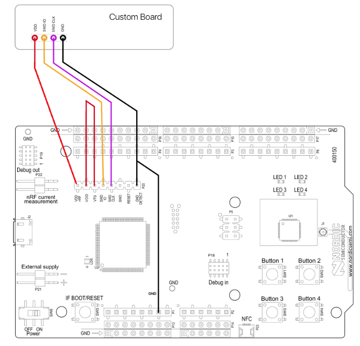
I’m attempting to program my board using the nRF Connect SDK, with the nRF52840 development kit as a more affordable J-link. I’ve wired it up like so (Image borrowed from this post):
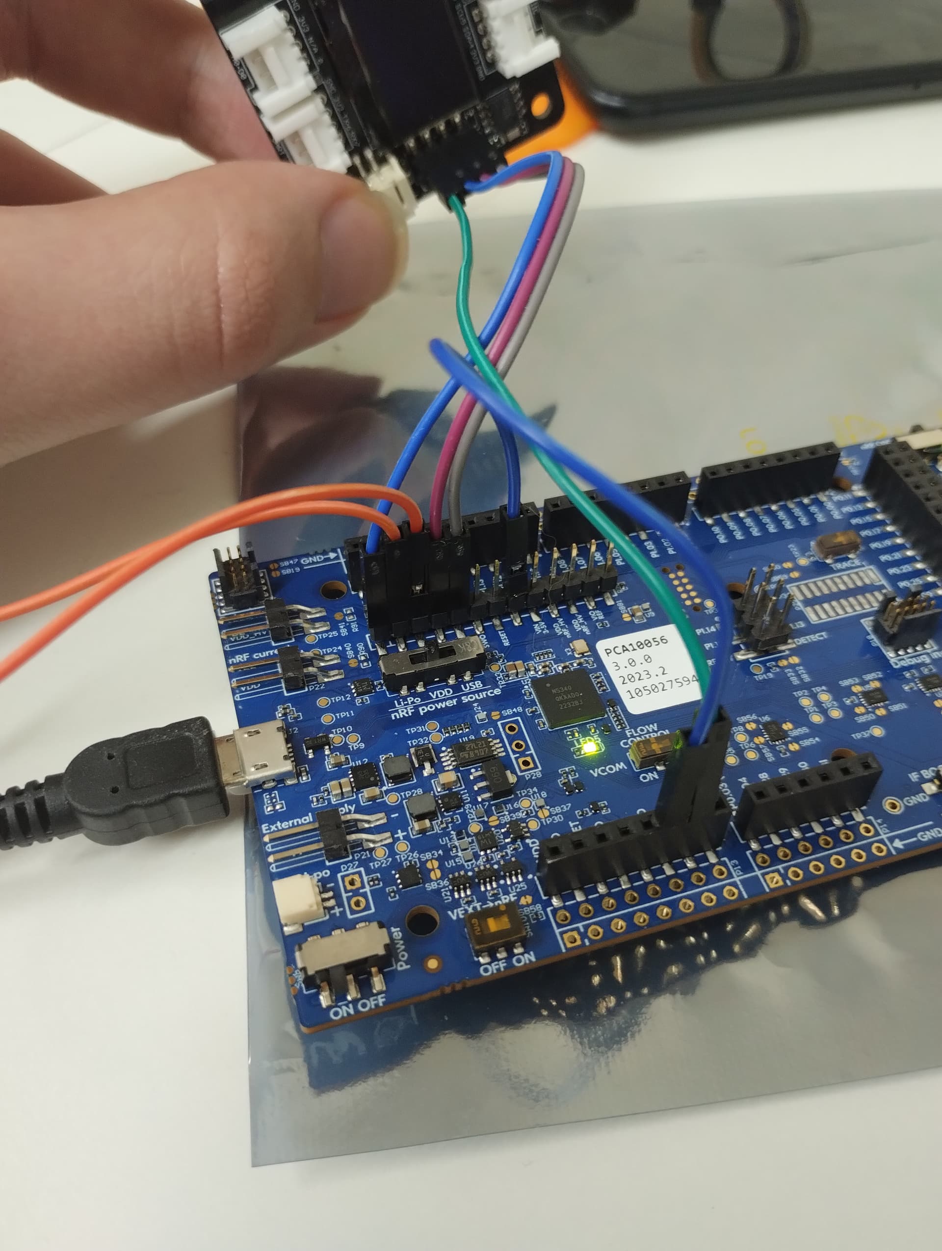
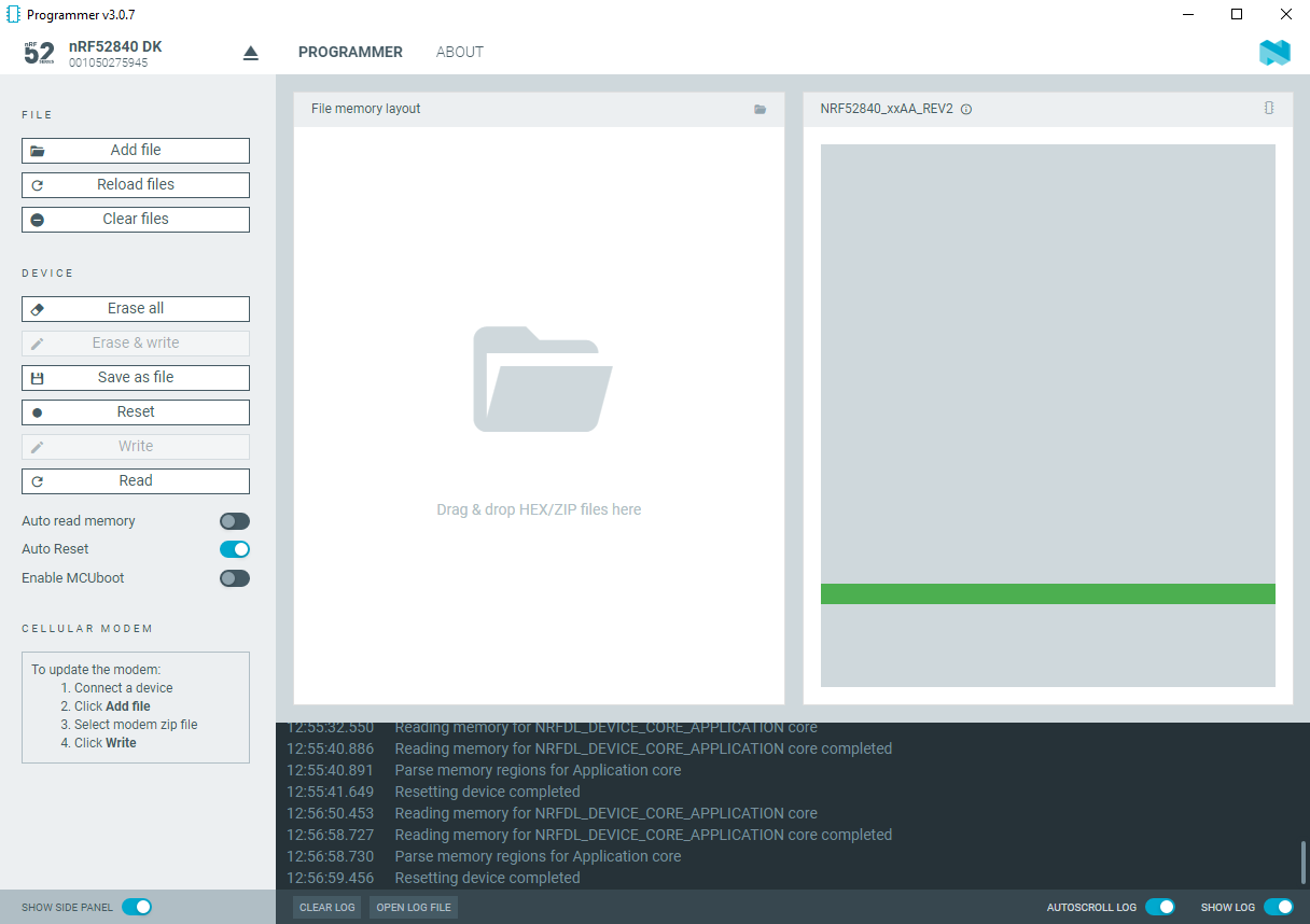
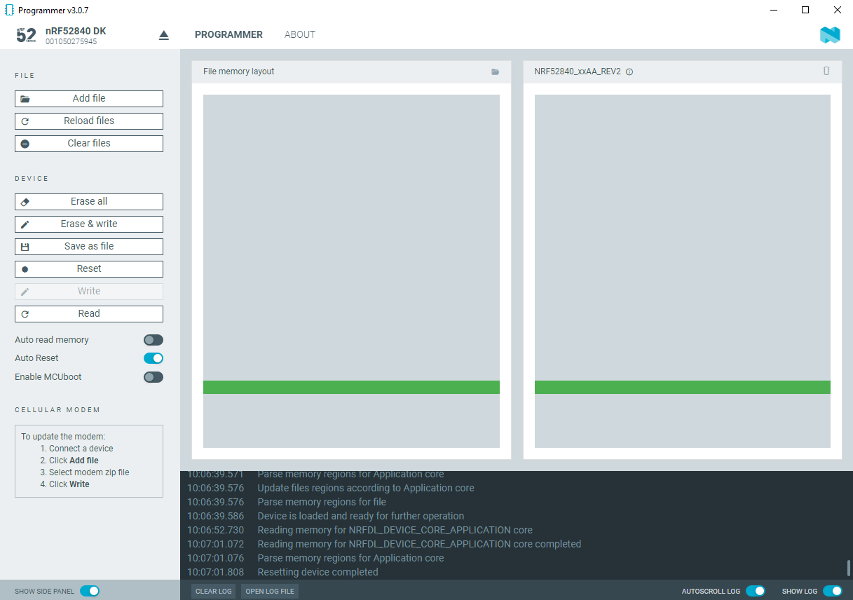
After connecting everything up, it looks like it should be working; I see in the terminal that the flash is programmed and verified, and it becomes unrecognized by Arduino afterwards so something happens, but it doesn’t appear to do what it should, even a basic blinking example. Have I connected everything correctly? I connected VDDnRF to 3v3 on the expansion board.
I am unsure what to make of this. The development kit I am using for its J-Link is running the Blinky example, and I’m assuming what I’m seeing is the kit rather than the board attached to it.
Figured it out with help from a Nordic dev; the board files were made for the old SDK and expect/leave room for a no-longer-needed SoftDevice. In xiao_ble_defconfig in the board files, I had to set CONFIG_BUILD_OUTPUT_UF2=n and CONFIG_USE_DT_CODE_PARTITION=n
thanx,
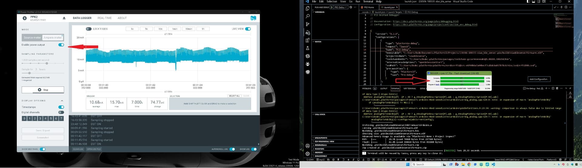
I haven’t had any chance to wrap my head around the SES stuff and pretty much hit the basics and get it done with VScode’s, PlatformIo and the debugging works perfectly. Arduino IDE 2.0 on the other hand, works ok but it’s like a toy with NO debugging and it’s annoying file open and Board and chip selection wacky code. It’s terrible such a great hardware and footprint design is SOooo hampered by the firmware and lack of any engineering Software support. (you only need look to the reply’s column’s in the Forums category index)
GL
Hey, PJ_Glasso;
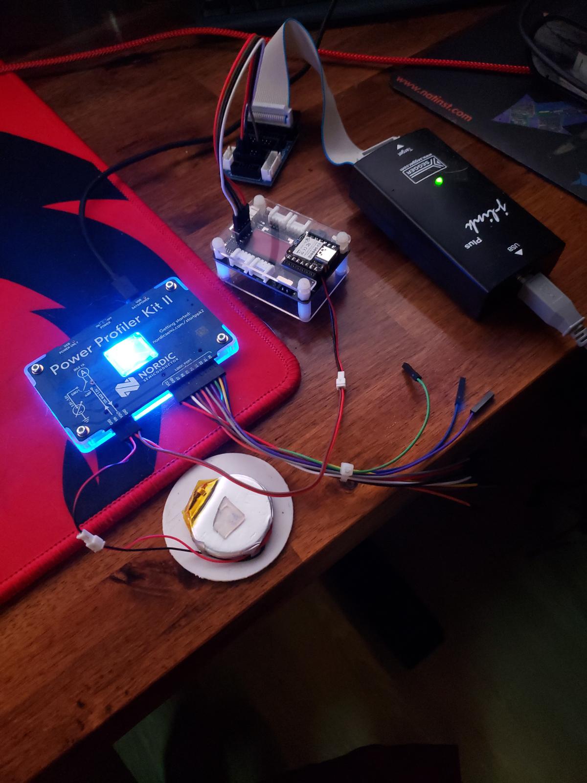
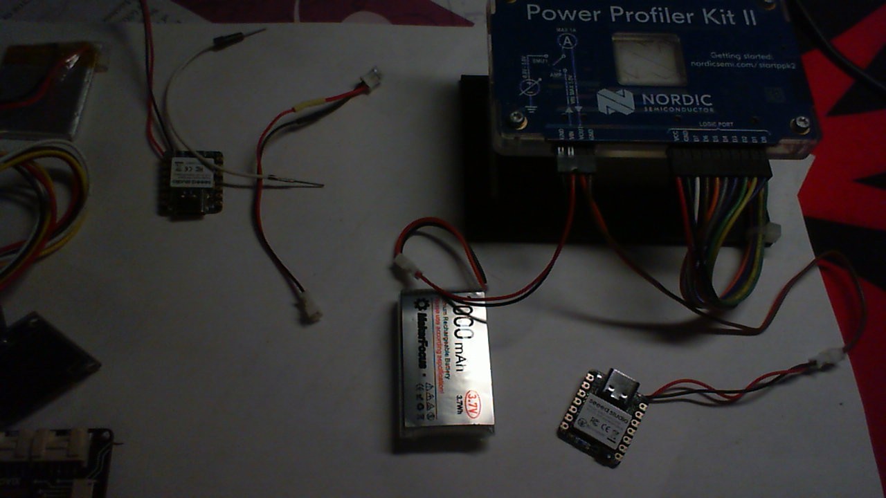
I am trying to connect XIAO seed studio with PPK2 to measure power consumption and see it on nRF desktop app.
I am connecting 5v pin of controller to Vout of PPK2 and GND of PPK2 to GND of controller(XIAO seed studio).
However, i am seeing current in microAmps instead of milliAmps.
and welcome here…
NO the battery PADS need to be connected to the PPK, check out my threads on it. Use the search
Best money ever spent, with all that it does too.
HTH
GL PJ
I have seen your thread. I understood the connection of ppk2 with battery(gnd and Vin) but i am confused as why did you connect +ve and -ve terminal of Xiao with Vout and Gnd of PPK2 ; why not use 5v and GND of Xiao instead? Can you clear my confusion?
SO maybe the picture will help, the circuit diagram Silkscreened on the PPK2 shows the Amp meter configuration. to see the flow through the Xiao from the Battery. This way the PPK appears to be the battery , Hence we can monitor the current going through it from battery to Xiao.