The Nano is the perfect candidate for automotive troubleshooting and other low frequency signal analysis. One reason that I am looking for more signal resolution is for automotive secondary ignition analysis which would use about 500us/Div for single cylinder analysis. Many clues can be gleaned from close ignition signal analysis as shown in the GIF1 attachment. The actual waveform is shown in GIF2 attachment. I am sure that there are countless other applications where advanced users could use more resolution at the display and more samples per second to find random trigger events while at T/Div more than 10us/Div.
Yes, we are using an HV probe (1000x @50Kv with it’s own chassis ground) but the Nano (with 1x probe setting) will display in volts not kilo-volts because volts is the input signal. The user has to understand that the display represents kilo-volts.
In this example, if the grid resolution were changed to 50w x 25h (pixels) then half as much waveform could be displayed, but if the sample rate were also doubled, then the waveform would have twice the resolution. The capture buffer used would be half as many samples at twice the normal sample rate for 500us/Div. The screen could be scrolled left or right to make up for the narrower viewing area. Instead of being able to scroll 13 screens, you can now scroll only 6 screens at half the information per screen (equivalent to 3 screens). This whole process would be called “Oversampling 2x mode”. Other oversampling rate options may also be viable.
In addition to seeing better resolution on the screen, the oversampling would increase the ability to find a desired trigger (random event). In the above example the sampling rate would increase from 50Ksa/s to 100Ksa/s.
You can do this today as sampling rate is tuned to choice of T/Div.
If you go from 200us/Div to 100us/Div, sampling rate gets doubled and the pulse (or whatever we look for) is stretched in the time domain equivalent to doubling the grid size from 25 to 50 along the horizontal axis.
You can not choose 250us, but 200us should be close enough and give you an even higher sampling rate.
Hello Lygra, sorry not been able to answer your mesage, I am attaching some ref. waves i took. They are few because I haven’t found a proper test lead, as you may know a vehicle’s engine produces large amounts of noise due to the ignition system, the alternator and so on.
An oscilloscope test lead will a perfect choice beaucase it has a screened cable and a x10 attenuation,but I’ve read somewhere that a X10 100mhz oscilloscope lead can’t be used with the nano due to the impedance, is that thrue?, Is there a way to supress the noise along with using a X10 probe in order to test higher voltages?. I have to say that I took some measurements to the fuel injector, and the Vpp was 75volts, and the nano’s max. voltage is 80Vpp, so whenever I test injectors I fear I can damage the Nano.
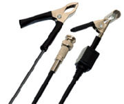
I agree with you I will also like to see the Nano been capable to mesasure the primary and secondary Kv, I wonder if it’s possible to use a secondary capacitive pickup probe, like the one in the picture?
Anothern thing is that it will be great if in the mesaurement option on the nano’s screen will be a Pulse width option (in miliseconds), that will be usefull when you test injectors and want to check the increase of the pulse width at idle and full throttle.
Thanks to BenF the Nano is a more versatile tool, and with your ideas of having a software dedicaded to the automotive field I think it will be taken to a upper level
(c) I never condoned a specific functionality for automotive use. BenF doesn’t agree with adapting to specific uses in the firmware and I completely agree with him. Any custom adaptation should remain with using the Nano file system.
(b) Thanks for those files. They point out that it would be good if we could load the capture buffer files instead of just loading REF files. Of course that may be a difficult to implement feature.
(a) I want to see what a 50-ohm terminator will do on the input of the Nano as far as volts accuracy is concerned. High frequency impedence will also come into play. I have a terminator on order along with a cap HV probe, so I’ll let you know what I find.
Got me on that one! And just when I was on a roll too! I think the trees got in the way of my forest. This concept would only prove useful for the 20us/Div setting where the sample rate appears to be 500Ksa/s; and may not be worth implementing.
Because the Nano V1 does not have a shielded case (not to mention unshielded test leads), it is important to keep it as far away from the ignition system ElectroMagnetic Interference (EMI) as possible.
For example, to measure the fuel injector signals, go back to the Engine Control Unit (ECU) and back probe the wires there. This will place the metal firewall between the Nano and the ignition system. It will also allow the feed-thru features of the ECU (feed-thru is designed to prevent EMI from entering the ECU while allowing the signal to enter) to help attenuate any EMI at that location.
The formula for T/Div (t) to sample rate (sa/s) is [color=red]sa/s = 25 / t where 25 is grid pixel width. At 20us/Div however this would require 1.25Msa/s which is beyond the Nano 1Msa/s max sampling rate capability. So for T/Div’s 20us, 10us, 5us, 2us and 1us we sample at the max rate of 1Msa/s. For all other T/Div’s there is a one-to-one ratio of pixels on screen and actual real-time samples. At a T/Div of 1us we would need 25Msa/s to maintain full resolution and so time scales 10us, 5us, 2us and 1us may seem unnecessary gven the Nano sampling speed limitation. Still these settings add value as they perform the equivalent of a zoom function (the waveform gets stretched in the time domain).
There is much more that can be said about sampling theory in general and its application in DSO’s specifically, but the essential bit to take away from this would be to realize that a T/Div of 20us (or less) is the preferred scale when we look for “high frequency” components in the input signal. This also applies to numeric measurements (such as probing for min/max values), since the higher sampling rate will enable narrow pulse detection and so account for these peeks in measurements. In comparison, the highly popular (and relatively expensive) Fluke 115B digital multi meter will sample at a maximum rate of 6000 samples per second. At this lower rate, it is not suitable for measuring the likes of narrow ignition pulses. With the Nano at 1Msa/s however we can do far better with respect to auto ignition/injection diagnostics.
Thank you for that insight and clarification. I guess I was trying to achieve what you just said in my own convoluted oversampling methods when all I had to do was use your procedure as described below in my own words.
It would be prudent to view at T/Div 20us (or less) when capturing a signal that would normally be viewed at 200us/Div if you are looking for high frequency components. Then you could scroll the trigger point to see the other portions of the waveform. This would give you maximum sample resolution on the Nano; correct?
I have also noted that the trigger level adjustment steps are visible at T/Div less than 10us, when the display jumps to the next trigger point on the display. In other words the triggered waveform jumps horizontally in sample-rate increments because it can only find trigger at sample time intervals. This can be observed by setting the Freq Out to 200Khz, Tr. Sens to 0, Tr.Kind to UP, and setting the T/Div to 1us. As you move the trigger level through the vertical dimension of the waveform, you will see the waveform jump horizontally to the next triggered sample point.
Thank you very much Lygra, I just got my ignition probe but still haven’t have the chance to use it (most of engines have coil-on-plug ignition), Can’t wait to try it.
I just saw your video #8, and I didn’t know you can measure current with the DSO Nanon ,How you managed to measure current ramp?, Did you use a low current clamp? if so, Can you post a picture of the current clamp?. Again thanks alot for your response.