OLED Display 0.96" (SSD1315) has wrong I2C Address (0x3c)

Hello,
I have 2 OLED Displays (0.96" - SSD1315) that seem to have the wrong I2C address. According to the wiki and the schematic the I2C address should be 0x78 by default. However when I use an I2C scanner program the display shows up with an address of 0x3c.
Why is that? Is the documentation incorrect or am I doing something wrong.
The I2C scanner I used is on this page:

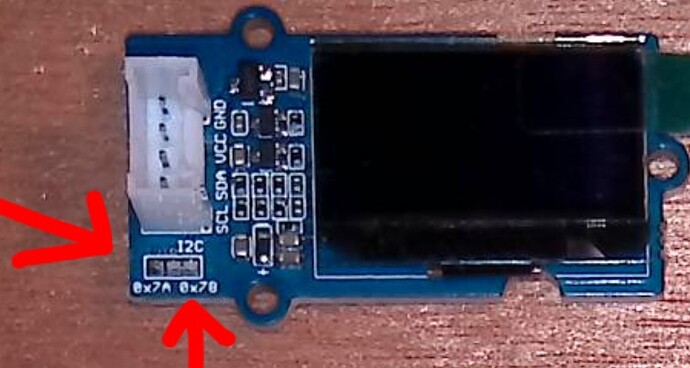
A second question I have is about setting the optional I2C address. There are 3 pads on the PC board for setting the I2C address. The center pad goes to D/C pin. Another pad is linked to ground through a 4.7k resistor. This pad has a small trace on the pc board connected to the D/C pin. The 3rd pin is tied to VCC through a 47k resistor. The schematic indicates “If the customer ties D/C# (pin 15) to VCC,
the I2C slave address will be 0x7a”.
My question is if I connect D/C to the VCC pad, do I cut the trace from the ground pad or leave it connected?

Not sure if it matters but I’m using a Seeeduino lotus board for this.

Thanks in advance for reading my post and helping me out!!

DarkStar
Hi Darkstar,
Same questions I have. Did you receive an answer? It’s January 2022, and no reply in this forum.

If it matters: the OLED works when I2C address ‘0x3C’ is used in (Circuitpython)code. So, you are correct. But I also do not understand the pads on the PCB. I’ll like to use them to change the I2C address, because ‘0x3C’ is used too often as I2C address by other OLED-displays.

Peter

Hello Peter,
I never got an answer to my question about the 0.96" OLED display i2c address. I gave up and just used the Grove i2c multiplexer which allows you to connect i2c devices with the same address to the i2c bus.

Hope that helps Peter!

Darkstar

Hi Darkstar,

Thanks for replying. A pity no answer is given. Also thanks for the tip.

However, I already know about the I2C multiplexer and used it with Raspberry PI. It is not ideal, I noticed that the multiplexer must be the only device on the I2C bus, apparently. I’ve tried to connect one OLED-display on the multiplexer and another one on the regular I2C bus… it did not work. Maybe it is the Raspberry PI and needs it further research. I’m a software- and not an electronic engineer.

Anyway, again thanks for replying, it helps.
Peter

I2C addressing consists of the address (7bits) plus a lower bit which indicates read or write. I have noticed several OLED devices give the address plus the read/write bit. For example:
0x78 is the address + read write, 0x78 / 2 (shift read write bit off) = 0x3C which is the address.

Using VCC one can drive the lower bit of the address high - making it 0x3D. (0x7A with read/write bit)

Hi @rickorensen,

Thanks for clarifying. Makes sense.

Attached is close-up photo of the I2C pads on the OLED-Grove shield. I see that pad 0x7B is closed with the middle pad.

If I understand you correctly, I have to interrupt the connection from middle pad to 0x7B pad and close the 0x7A pad with the middle pad to have I2C address ‘0x3D’. Correct? Could you confirm?

Note: I do not see the pads in the schematics or PCB provided by Seeedstudio.

Update: for whatever reasons the mailings continues via email. SeeedStudio support has answered that indeed cutting the trace and connecting the other trace is correct. I’ll do that as soon as I have made time for it.

Kind regards, Peter

Hello Peter,
I should have mentioned that after a month of no response I went ahead and cut the trace and moved the jumper on one of my displays. The address didn’t change. That’s when I gave up and used the i2c mux.
I’ve suspected that I may have defective units so it will be interesting to see if moving the jumper changes the address for you.
The other issue that has not been answered is why does the schematic, the wiki, and the silk screened legend on the pc board indicate the default address is 78 but it is actually 3c? Since the board you have also is addressable at 3c I suspect you’ll get the same results I did, the address won’t change. I’m hoping I’m wrong. Please let us know how it goes.
One other note, 0x3c is half of 0x78 so that leads me to believe there is a higher order address bit not correctly set. There is probably a simple defect in the layout of the board causing the issue.

Thanks!
DarkStar

One of life’s most puzzling puzzles:

   Is the address 0x78 or is it 0x3C?

Answer: Both of the above, depending on your Point of View.

Data sheets almost always give the I2C device address as a 7-bit number. For these devices, the 7-bit device address depends on the jumper setting, and is either

  • Binary 011 1100 (Hexadecimal 0x3C)

      or
    
  • Binary 011 1101 (Hexadecimal 0x3D)

I note that many of the Data Sheets only give 7-bit binary values and leaves the user to figure out what the Hex values are, depending on how they may be used in an application’s software routines.

Here’s an excerpt from the Data Sheet for an SSD1306:

Either “0111100” or “0111101”, can be selected as the slave address of SSD1306.

Consider the first configuration:

Now on the I2C bus, the first byte after putting the I2C “Start” condition on the bus goes like this:

For beginning a “Write” transaction, the device address is shifted left one bit, giving binary 0111 1000 (hexadecimal 0x78). For a “Write” transaction, the LSB (Least Significant Bit) is left as ‘0’. For a “Read” transaction the LSB is set to ‘1’.

Just about all of the professional (and almost-professional) software libraries that I have used — Circuit Python, Micropython, and lots (and lots) of C/C++ libraries for Raspberry Pi and approximately a gazillion Microchip PIC processors— use the 7-bit address when calling I2C libraries.

On the other hand:

I have seen posts where individuals have written library routines that use 0x78 (binary 0111 1000) as the address parameter in the calling routine, and the library function sets the Least Significant Bit for reading.

Bottom line: If your I2C scan program shows 0x3C, it is consistent with the silkscreen 0x78 label. If you change your board to use the 0x7A position (8-bit binary 0111 1010), (and you did it right) you should see 0x3D as the I2C device address in your I2C scanner program.

Regards,

Dave