Grove IMU 10DOFv2 wire directly to arduino header (GND to pin 9, VCC to pin 1, white SDA to pin 3, yellow SCL to pin 5)
I installed the library from https://github.com/Seeed-Studio/Grove_IMU_10DOF_v2.0/archive/master.zip and tried running the example code. accelgyro.initialize() runs fine, the next call to bmp280.init() never returns. I tried calling setSampling() (empty param list to use all default values) before the init() call but that didn’t help.
It still doesn’t return from the bmp280.init() call.
Hi @Mitch_Faatz
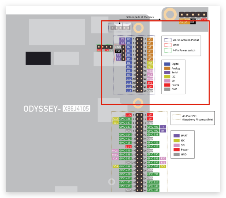
Did you connect properly? From your description, you seem connected to the 40 pin GPIO which is not the Arduino Pins. The 28 pin is Arduino Pins:
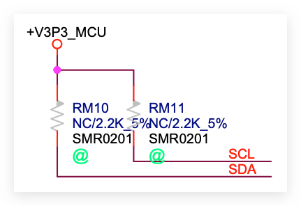
Is there a pullup resistor 4.7k on SDA and SCL?
need to pull up ro +3.3v
Just checked the schematics, and it was on the schematics but not solder on:
But the SAMD21 core has internal pull-up resistor:
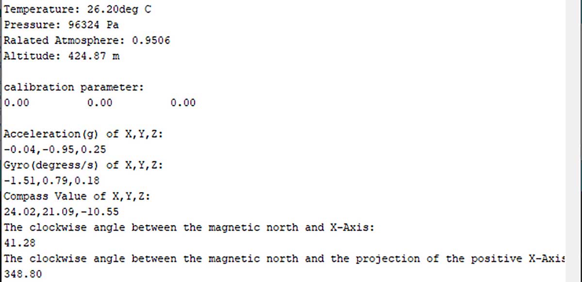
Good catch! I was looking at the GPIO pinout diagram for some reason. Now that I have it hooked up to 28 (GND), 24 (3.3v), and the two i2c lines to 14 and 16, init returns now. However, it says “MPU9250 connection failed” but I get data updating (what looks like) properly:
So I do need pullup resistors on SCL and SDA? I figured the little Grove board would have those surface mounted.
Yes, for grove that is fine.
So now pull-up resistors are needed for the Grove board. Still the unexplained “MPU9250 connection failed” message then.
Hi @Mitch_Faatz
Can you screenshot the message of “MPU9250 connection failed” , where does it appear this message? In the Serial monitor? And when did it appear(at the beginning of initialising?)
And you do not need pull-up resistors for Grove. The answer above for marki is considering not using Grove.
Sure, and here is the slightly modified code from the 10DOF example sketch (I just added some debugging output):
// initialize device
Serial.println(“Initializing MPU9250 I2C device…”);
accelgyro.initialize();
Serial.println(“Setting BMP280 I2C device sampling values…”);
bmp280.setSampling();
Serial.println(“Initializing BMP280 I2C device…”);
bmp280.init();
Hi @ansonhe97
Just so I’m 100% clear on the osyssey x86 arduino I do not need pull-up resistors on the I2c bus?
I’m doing my board layout now and will remove the resistors if you confirm
Thx
Mark
You still owe me an external software reboot from x86 
Hi @Mitch_Faatz
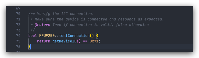
Just had a look at the code and it seems it’s coming from here:
Can you print Serial.println(accelgyro.getDeviceID()); and check the value please?
Hi Mark,
What I meant was, the SAMD21 on Odyssey board does not have pull-up resistors for I2C buses(not soldered on and SAMD21 internal pull-up is weak pull ups). I would recommend to have your own I2C pull-up resistors for your board.
Grove module itself has pull-up resistors on the module.
Yes, our team is still working on this, hope everything else working fine 
Hi @ansonhe97, interesting, it returns zero.
Just to double check, I just wired directly GND to pin 28, VCC to pin 24, SCL (yellow) to pin 16, and SDA (white) to pin 14.
I wonder if my IMU 10DOF is defective?
If you have another Arduino board, you may get it a go? Or can you power the module using 5V pin and see if that makes any difference?
Seeed: MPU950 DeviceID returns 0, MPU9250 Connection Failed, Calibration parameters are 0.0 0.0 0.0
Arduino Uno: MPU950 DeviceID returns 71, MPU9250 Connection successful, Calibration parameters are -1.00 27.00 -11.00
So all good on the Arduino Uno. Problem is something specific to the J4105.
Parts are coming from the Factory to the office this week, sorry for the long response, will get back to you this week.
Sorry to be so late to response, have tested and updated the code in Github. Please update the library to the newer verison