Odd USB serial port behavior when XIAO-ESP32C6 is connected to an RD-03E radar sensor

Hi Folks,
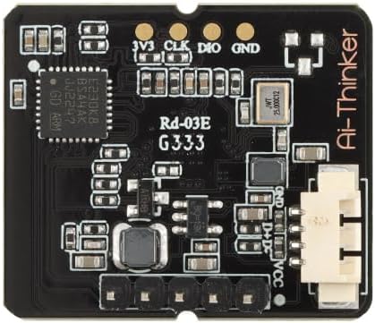
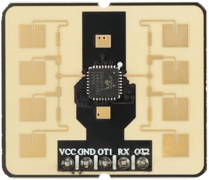
I’ve been playing around with the RD-03E radar sensor. I’m using a XIAO-ESP32C6 to connect to the radar module. The oddity I’m seeing with the USB serial port is as follows. I first connect my xiao to the radar module. Upon doing so I can compile and upload code to the module. From the debug info I can see that the xiao is sending the proper command string to the radar module but the radar module never responds. However, if I unplug the USB cable and plug it back in, I start to see responses from the radar module. This behavior is consistent across three separate programs that I’m using for testing (one reads the radar module firmware version, another sets the module up for distance calibration). Here is some output from the serial port monitor:

Setting Distance Calibration...
Enable Configuration ACK: 
Enable Configuration ACK not received.

Setting Distance Calibration...
Enable Configuration ACK: 
Enable Configuration ACK not received.

***HERE IS WHERE I DISCONNECT AND RECONNECT THE USB CABLE

Setting Distance Calibration...
Enable Configuration ACK: 0xFD 0xFB 0xFA 0x08 0x00 0xFF 0x01 
Distance Calibration ACK: 0x00 0x00 0x01 
Distance Calibration Command successful.
Configuration Ended.

Here is the associated code:

// RD-03E Radar Sensor Calibration code
// JCL, 10July2025
// https://www.electroniclinic.com/rd-03e-mmwave-human-detection-sensor-with-esp32-distance-measurement-hand-gesture/#Rd-03E_Arduino_Library

#define RX_PIN 17 // for ESP32C6  
#define TX_PIN 16  
//#define RX_PIN 44  // For ESP32S3
//#define TX_PIN 43
 
HardwareSerial radarSerial(1);  // Use Serial1 for the RD-03E radar module
 
void sendCommand(uint8_t *command, size_t length) {
    radarSerial.write(command, length);
}
 
void enableConfiguration() {
    uint8_t enableCommand[] = {0xFD, 0xFC, 0xFB, 0xFA, 0x04, 0x00, 0xFF, 0x00, 0x01, 0x00, 0x04, 0x03, 0x02, 0x01};
    sendCommand(enableCommand, sizeof(enableCommand));
    delay(100);
}
 
void endConfiguration() {
    uint8_t endCommand[] = {0xFD, 0xFC, 0xFB, 0xFA, 0x02, 0x00, 0xFE, 0x00, 0x04, 0x03, 0x02, 0x01};
    sendCommand(endCommand, sizeof(endCommand));
    delay(100);
}

void setDistanceCalibration(int32_t calibrationValue) {
    // Step 1: Enable Configuration
    enableConfiguration();
    delay(100);
    Serial.print("Enable Configuration ACK: ");
    bool enableAckDetected = false;
 
    // Check for Enable ACK (0xFF 0x01)
    while (radarSerial.available()) {
        uint8_t byte = radarSerial.read();
        if (byte == 0xFD && radarSerial.read() == 0xFC) {
            enableAckDetected = true;
            Serial.printf("0x%02X ", byte);
        } else if (enableAckDetected) {
            Serial.printf("0x%02X ", byte);
            if (byte == 0x01) break;
        }
    }
    Serial.println();
 
    if (!enableAckDetected) {
        Serial.println("Enable Configuration ACK not received.");
        return;  // Exit if Enable ACK not received
    }
 
    // Step 2: Send Distance Calibration Command
    uint8_t calibrationCommand[] = {
        0xFD, 0xFC, 0xFB, 0xFA,  // Frame Header
        0x08, 0x00,              // Intra-frame Data Length (8 bytes follow)
        0x72, 0x00,              // Command Word for Distance Calibration
        0x00, 0x00,              // Distance Calibration Parameter Number
        (uint8_t)(calibrationValue & 0xFF),         // Calibration Value byte 1
        (uint8_t)((calibrationValue >> 8) & 0xFF),  // Calibration Value byte 2
        (uint8_t)((calibrationValue >> 16) & 0xFF), // Calibration Value byte 3
        (uint8_t)((calibrationValue >> 24) & 0xFF), // Calibration Value byte 4
        0x04, 0x03, 0x02, 0x01   // End of Frame
    };
    
    sendCommand(calibrationCommand, sizeof(calibrationCommand));
    delay(200);
 
    // Step 3: Read and confirm Distance Calibration Response
    Serial.print("Distance Calibration ACK: ");
    bool calibrationAckDetected = false;
 
    while (radarSerial.available()) {
        uint8_t byte = radarSerial.read();
        Serial.printf("0x%02X ", byte);
        if (byte == 0x01) {  // Confirm ACK end
            calibrationAckDetected = true;
            break;
        }
    }
    Serial.println();
 
    if (calibrationAckDetected) {
        Serial.println("Distance Calibration Command successful.");
    } else {
        Serial.println("Distance Calibration ACK not received.");
    }
 
    // Step 4: End Configuration
    endConfiguration();
    delay(500); // JCL: Changed from 100 to 500
    Serial.println("Configuration Ended.");
}
 
void setup() { 
    Serial.begin(115200);
    radarSerial.begin(256000, SERIAL_8N1, RX_PIN, TX_PIN);
    delay(1000);
}
 
void loop() {
    // Set distance calibration (example value of 100)
    Serial.println("Setting Distance Calibration...");
    setDistanceCalibration(100);
    
    Serial.println("");
    delay(4000);
}

Thank you!

Jim

Since making this post, I’ve determined that I can get the radar module to output serial data without disconnecting the USB cable. Instead I’ve found that I can disconnect the power to the radar module and upon reconnecting the power, the device starts spitting out data. I take this to mean that the serial comms problems I’ve been seeing are within the RD-03E radar sensor module itself.

Hi there,

So Interesting problem, I have tested some of them, not this specific one though.(full disclaimr) :grin:

Which module is this? Do you have a link?
This sounds like the RD-03E is getting powered before UART on the ESP32C6 is fully ready — or it’s expecting a quiet line before responding, by power-cycling the radar likely resets its internal serial state.
You might try resetting the radar with a GPIO line after the Serial.begin(), and add a short delay, and flush the serial buffer. Some sensors are picky about timing during boot!

HTH
GL :slight_smile: PJ :v:

1 Like

Thank you, once again, PJ! - Jim

1 Like

Hi there,

No problem, Something along these lines if so?

#define RADAR_RESET_PIN 10
pinMode(RADAR_RESET_PIN, OUTPUT);
digitalWrite(RADAR_RESET_PIN, LOW);  // Hold in reset
delay(100);
digitalWrite(RADAR_RESET_PIN, HIGH); // Release
delay(100);

HTH
GL :slight_smile: PJ :v:

1 Like

PJ - Here is some information specific to the RD03-E radar module I purchased:

Manufacturer ‏ : ‎ EC Buying 

Rd-03E is a radar module equipped with the S3KM111L chip and the S3KM111L chip of Silicon Microelectronics. S3KM111L is an integrated single-chip millimeter wave sensor SoC based on FMCW radar transceiver technology. It operates in the K band of 24 GHz, with a modulation bandwidth of up to 1 GHz for each single frequency scan. This module adopts FMCW waveform and advanced signal processing technology exclusive to S3 series chips, combined with MCU exclusive radar signal processing and built-in intelligent presence sensing algorithm, to achieve accurate human body sensing distance measurement and gesture recognition. Developers can display real-time distance information and gesture information through upper computer tools.
The Rd-03E module can detect and recognize moving and micro moving human bodies, and report real-time distance. It can detect targets and gestures in designated areas and report results in real time. It is widely used in various AloT scenarios. This module has the characteristics of strong real-time performance, high ranging accuracy, large ranging range, and flexible algorithm parameter configuration.
Adopting DIP packaging, standard 2.54mm pin arrangement
The radar supports the 24GHz ISM frequency band
Accurate detection of indoor and outdoor human movement, micro motion sensing and distance, and gesture recognition
The radar antenna supports 1 receiver and 1 transmitter, with narrow beam width, high resolution, wide frequency band, and strong anti-interference ability

Model: Rd-03E
Packaging: DIP-5
Size: 28.0 * 24.0 (± 0.2) mm
Antenna form: onboard antenna
Spectrum range: 24G~24.25GHz
Working temperature: -40 ℃~85 ℃
Storage environment: -40 ℃~125 ℃,<90% RH
Power supply range: Power supply voltage 5V, power supply current ≥ 200mA
Supported interface: UART
Serial port speed: default 256000 bps

I tried to look at the PDF , data-sheet , no go…
Can you post a pic of the setup :+1:

GL :slight_smile: PJ :v:

Does this help?

https://www.amazon.com/EC-Buying-Movement-Precision-Positioning/dp/B0D3CXT9JD?crid=2U0U8T5J0V3ZT&dib=eyJ2IjoiMSJ9.3y4zgE33uUjAfBVz56f6DQV1RBEcF2_bJLbHQeN-HTglTvEK1AT_H2MBTNn7WaOFgsy5pfQgXbrGLKtzDb4YH5vzelNcqj7-0dmrnX0NsGvAAYF2aYmQJUxNjWwjucNKv4GZ9P4rQo-GGrG7Dim29zFPpfQE1cZImiyq-aEdviBHEPesnf9zIbkygrw5JXG0sjdL8J9Ncg0MqsVUxfo6J9LsVMsBX-zEA_BQDnCk3xn1JNXdp9D9_dvOfYI3W-gsBKzt_svS_v5g9ndyPG4ppep_p0nXJ1X_d33QkF-u4sQ.MEFN62Vc4YkqJ17GsU7gpsariiRBEXAT4V994nkMwzA&dib_tag=se&keywords=RD-03E&qid=1752287874&sprefix=rd-03e%2Caps%2C170&sr=8-3

Perhaps, I see the OT1 & OT0
The strange is the Power, somewhere it say s 5V, but I see on the pads 3V.3, CLK, DIO, GND… , so maybe both.


the pins at the bottom are different

VCC (5V), GND, OT1, RXD, OT2
One may be a reset ? and used to sync up the response?
I see a grove connector, so maybe I2C also:v:, scratch_that I see now,
GND, D+ , D-, VCC on the silk screen

1 Like