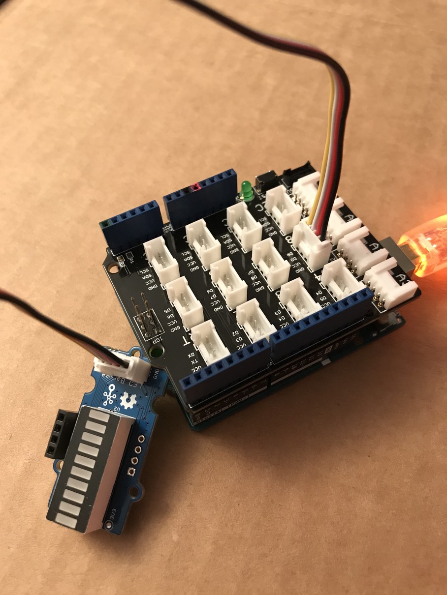
I have the following setup:
Arduino Uno
Grove Base Shield for Arduino (v2, I think)
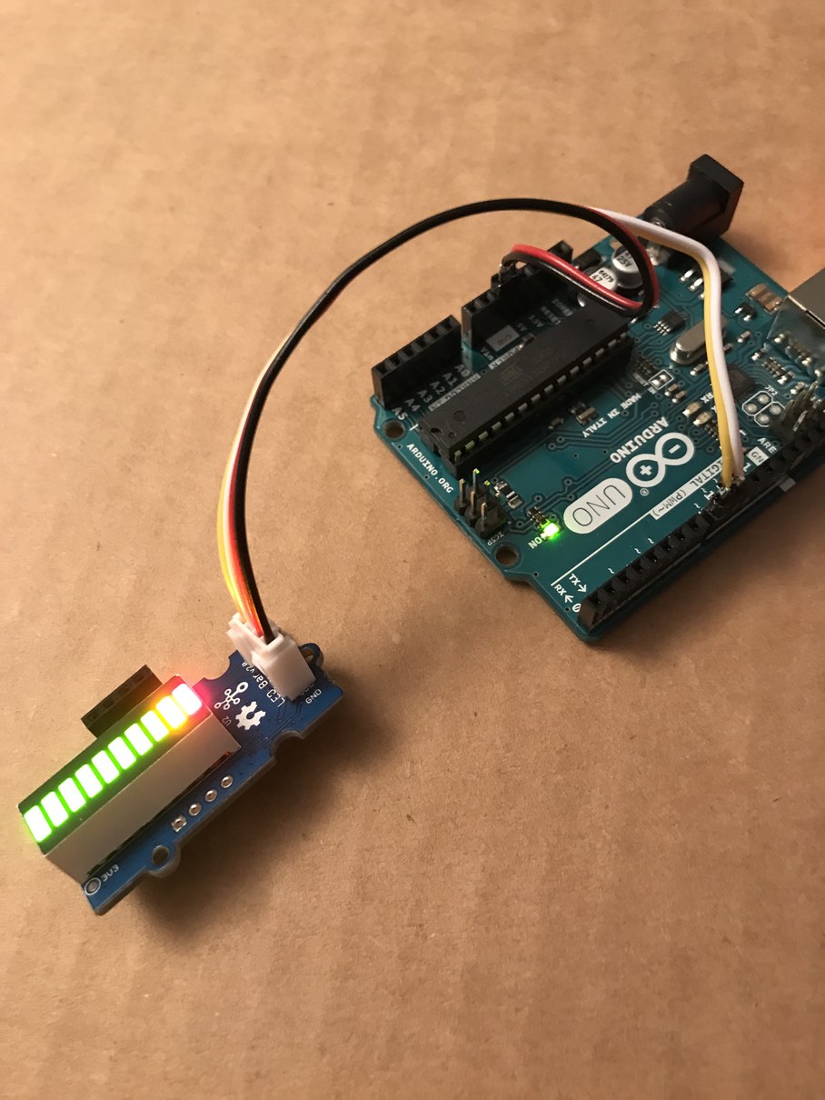
Grove LED Bar v2
-
If I…
…have just the base shield attached to the Uno (and not LED bar),
Open the Arduino IDE
Open the blink sketch
(the sketch doesn’t matter - just need something to upload)
And then upload the sketch…
…the sketch is uploaded and everything is fine -
If I…
…have the base shield attached to the Uno
…and also have a Grove LED button attached to one of the digital ports, say D2
Open the Arduino IDE
Open the blink sketch
And then upload the sketch…
…the sketch is uploaded and everything is fine -
If I…
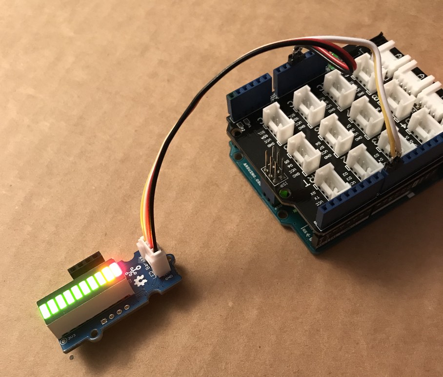
…have the base shield attached to the Uno
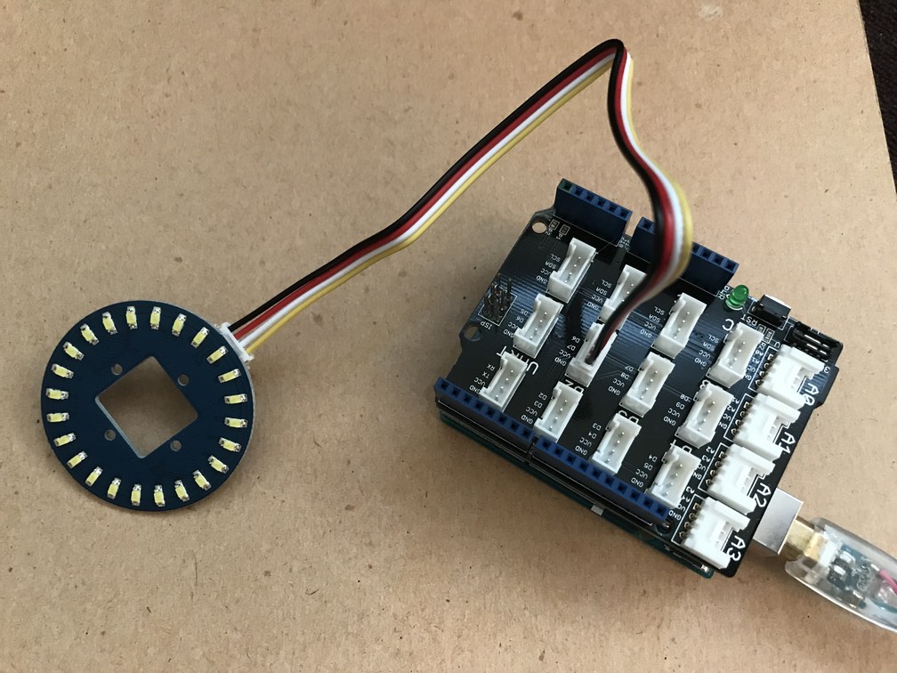
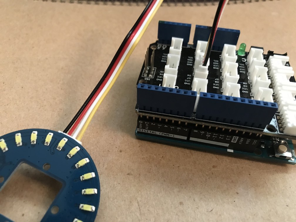
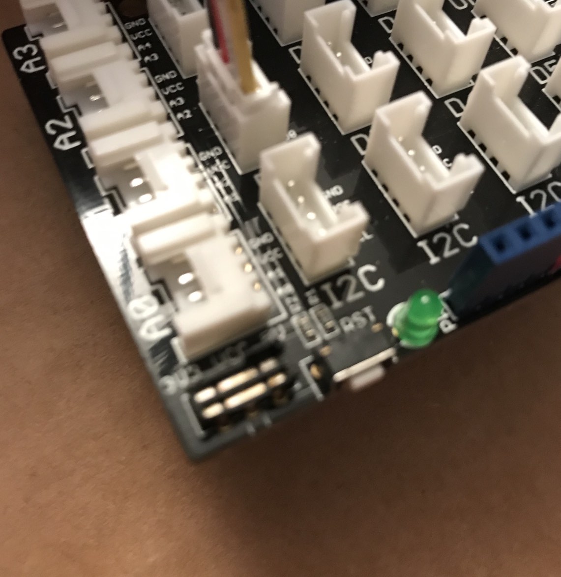
…and also have the Grove LED Bar attached to one of the digital ports, say D2
Open the Arduino IDE
Open the blink sketch
And then upload the sketch…
…I get the following error:
(and this is with verbose output during upload on)Using Port : /dev/cu.usbmodem1411 Using Programmer : arduino Overriding Baud Rate : 115200 avrdude: stk500_recv(): programmer is not responding avrdude: stk500_getsync() attempt 1 of 10: not in sync: resp=0x00 avrdude: stk500_recv(): programmer is not responding avrdude: stk500_getsync() attempt 2 of 10: not in sync: resp=0x00 avrdude: stk500_recv(): programmer is not responding avrdude: stk500_getsync() attempt 3 of 10: not in sync: resp=0x00 avrdude: stk500_recv(): programmer is not responding
- I’ve tried plugging the LED Bar into different digital ports, but I always get the same error.
- I have 2 of the Grove LED bars, and I’ve tried both, in different ports, but always get the same error.
If I then unplug the LED bar, I’m then able to upload the sketch.
Any idea as to what’s going on? And how to fix it?