Hello Everyone,
I am just trying out a very basic code to fade an LED using the XIAO nRF52840 Sense and it is not working !! I am using a potentiometer on Analog Pin A0 to read the analog value and fade the LED connected to Pin 9. When using the multimeter I see only .3V on the Pin 9. I am not sure what am I doing wrong as things cannot be more basic then this. Please help.
Code
const int LED = 9;
const int analogInput = A0;
int inputVal = 0;
float mv_per_lsb = 3300.0F / 1024.0F;// 10-bit ADC with 3.3V input range
So we see this question from time to time, paying attention to what others have pointed out… Here is easy example to try. Connect the Pot to “A0” , Pin 1 . there’s also some serial print info you can comment out, after you make any adjustments.
If you use the Code tags above “</>” just paste it in there, it makes it easier to read and for other to comment. You’ll get better help that way also.
Turning the potentiometer should smoothly fade the Red LED from OFF to full brightness.
You can extend it to mix RGB by mapping different ranges if you want full color fade.
// REV 1.0 - Xiao nRF52840 RGB LED Fader + Serial Debug

#define POT_PIN A0           // Analog input from potentiometer
#define RED_LED_PIN   11     // Onboard RGB Red
#define GREEN_LED_PIN 12     // Onboard RGB Green
#define BLUE_LED_PIN  13     // Onboard RGB Blue

void setup() {
  Serial.begin(115200);
  while (!Serial);  // Wait for Serial monitor to open (optional for debugging)

  analogWriteResolution(8);  // Ensure 8-bit PWM output

  pinMode(RED_LED_PIN, OUTPUT);
  pinMode(GREEN_LED_PIN, OUTPUT);
  pinMode(BLUE_LED_PIN, OUTPUT);

  Serial.println("RGB LED Fade Test - Xiao nRF52840 Sense");
}

void loop() {
  int potValue = analogRead(POT_PIN);           // 0–1023
  int brightness = map(potValue, 0, 1023, 0, 255); // Map to 8-bit PWM

  // Set RED LED brightness, turn others off
  analogWrite(RED_LED_PIN, brightness);
  analogWrite(GREEN_LED_PIN, 0);
  analogWrite(BLUE_LED_PIN, 0);

  // Debug output
  Serial.print("Analog Read (A0): ");
  Serial.print(potValue);
  Serial.print(" | PWM Brightness: ");
  Serial.println(brightness);

  delay(100);  // Update rate
}
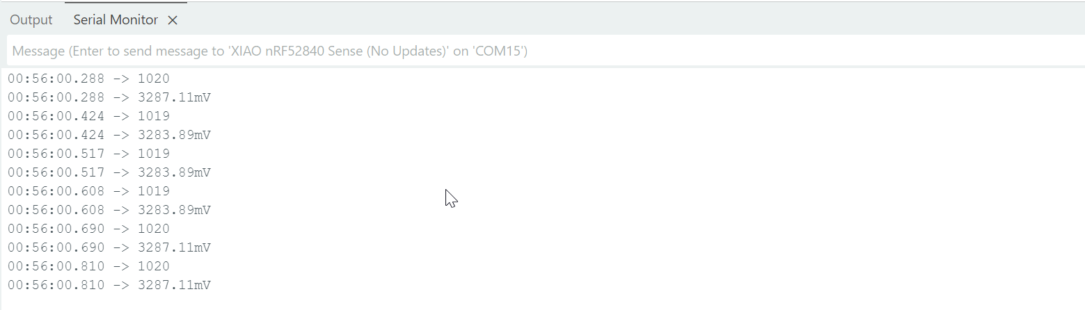
you get this at the serial port:
RGB LED Fade Test - Xiao nRF52840 Sense
Analog Read (A0): 87 | PWM Brightness: 21
Analog Read (A0): 624 | PWM Brightness: 155
Analog Read (A0): 1015 | PWM Brightness: 253
Thanks a lot for the code ! This works great using the Inbuilt LED but not able to achieve the same when using a LED on the Digital Pin 9 or any other digital pin. Interestingly my R/G/B pins as 12,13 and 14 respectively. I rechecked the soldering on the header pins and all look good to me.
Thanks for the quick response ! I am for some reason not able to get the LED attached to Pin 9 to fade even with the AnalogWriteResolution(8), This is working with the builtin LED with out without the resolution set to 8bits.
ashu15645,
If you connect external LED to pin D9, #define LED_PIN D9
and it should work.
As you probably know, external LED require a current limiting resistor is required.
@msfujino Thanks a lot for your advice ! Using the statement #define worked and I am able to fade the external LED. Yes, even without the current limiting resistor it works since reference voltage is 3.3V, but as you said always a good practice to have the current limiting resistor.
Thanks. I did try with 1.14 and it did not work but using #define D9 as suggested by msfujino worked ! I am using the nrf52 mbed enabled-board to avoid issues with the Serial commands.