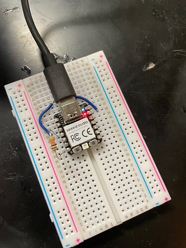
I hope I’m just missing something very simple or fundamental code-wise or in terms of wiring, but I’ve been pulling at my hair on this since last night. I have the following code which I initially wrote to try to drive the gate on a logic level FET to determine whether I’d need a driver or not (and yes, that wasn’t necessarily the best approach to what I’ve been working on but shipping times aren’t friendly and event dates are approaching), but it quickly evolved into me realizing that I wasn’t getting any sort of discernable output from the pins on my XIAO.
As I just joined the code is copy-pasted here:
void setup() {
// put your setup code here, to run once:
pinMode(6, OUTPUT);
pinMode(3, INPUT);
Serial.begin(9600);
}
void loop() {
// put your main code here, to run repeatedly:
digitalWrite(6, HIGH);
Serial.println(digitalRead(3));
// delay(1000);
// digitalWrite(5, LOW);
// Serial.println(digitalRead(5));
delay(1000);
digitalWrite(6, LOW);
Serial.println(digitalRead(3));
delay(1000);
}
I followed this guide for setting up Arduino IDE. I tested it out a few weeks ago with just the library for Adafruit’s BNO055 (though that just used I2C rather than needing any additional connections or logic) and it seemed to work fine. I went and tried hooking up a different XIAO RP2040 to try to trigger the FET gate yesterday and no dice. Grabbed the multimeter, the 3.3V pin was spitting out the appropriate voltage relative to ground but the digital pins read nothing. 0V. ![]() . Even after switching to analogWrite() and redefining the output pin as AX.
. Even after switching to analogWrite() and redefining the output pin as AX.
As of right now, the code is set up for a simple pull-down circuit (the wire going around back to GND under the USB port is just two wires and it does pass a continuity test. The Serial monitor is just spitting out a series of 0s (to be expected with no voltage output out of the board).
Is there something with the code? How I’ve defined anything? Are there other things I should import? Or things I’m missing based off USB power or whatever?
