what does debug output have to do with anything?
it will run with 3v3 from XIAO… apparently it has some type of voltage regulator buck converter on it i didnot notice dark screen either… I used a 4 wire to grove connector and had no problems
maybe they just have the TX & RX reversed… sometimes they print it backwards on the silk screen… and sometimes they put it pins in the wrong order in the code…
Ok, so it’s this:
- Easy to Use: Nextion HMI display connects to peripheral MCU via TTL Serial (5V, TX, RX, GND) to provide event notifications that peripheral MCU can act on, the peripheral MCU can easily update progress, and status back to Nextion display utilizing simple ASCII text-based instructions.
?
if so you need a level shifter, the Xiao’s are ALL 3.3vdc Devices.
That’s all that’s required, if the code compiles.
HTH
GL ![]() PJ
PJ ![]()
Only that commenting out the debug output def disables the “ESP multi pass-through Ready” message that PJ said would be the only output of the posted code.
To PJ_glasso: Yes, my current suspicion is that only a level-shifter is needed to get this working correctly & that the 2 boards that did work were probably “riding on the razor’s edge” between having high enough IO drive to register on the screen & not. … This is actually a fairly common issue that comes up all too often on Arduino support from users using 3.3v devices with 5v peripherals that only certain individuals will work because of the IO-voltage being in the “grey zone” for registering on one of the devices.
Yes, based on this is not available with a xiao that way…
if it’s in debug mode (commented out) that would and probably was the case , I’m betting. ![]()
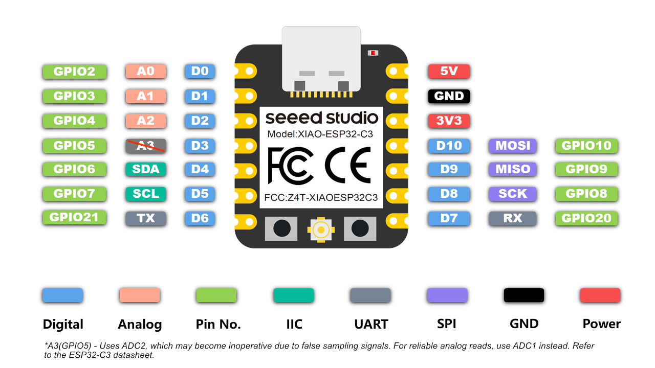
You want to use the TX and RX pins on a XIao (6&7) You can define more, but those are what works with the Serial(usb) port as well.
just incase you didn’t know. NO pin 20 or 21
ok… what XIAO are we talking about here… USB serial is Serial 0
the UART is Serial1 on TX&RX
you have it backward
I find the XIAO ESP32C3 is the best to prototype with
yes, unfortunately there were several boards being traded around…iirc, I wrote that code on one of my noname esp32c3 supermini boards. …Either way, only the comments would be wrong as the arduino core add-on contains defs for “RX & TX” as the UART0 default RX & TX pins for whichever board is selected in the IDE.
Correct sir, ![]()
level shifter on TX and RX and Go! maybe…LOL ![]()
the first problem is you cannot assume a generic ESP is the same as a Seeed XIAO … and it is not fair to us to waste our time troubleshhooting … its like saying … oh by the way… i am using a Mac… What Da?
no need for level shifter
well, tried to send a pic, but forum says I can’t post links or embed images, so there’s that.
yes… unfortunatly that is a scammer prevention thing… you can post after you level up your membership
Yea, it is some spammer control, a couple more posts and reply’s 3-10 ?
@cgwaltney had one of these and had it working I think with the C3 so test the code I posted (working SoftSerial pass-through) see if anything comes across. when you send the string from a treminal program.
![]()
PJ
I would also think a Serial to TTL converter would allow you to test the hardware standalone too.
irl interruption…will prob. try sending to the screen from a C applet on my linux box when I get back to it… use the ch340 bridge on one of my MEGA2560 boards.
Supposedly that screen requires 3 0xFF bytes following a string to display?
I would try this and see if you get some output
#include <SoftwareSerial.h>

#define SOFT_RX 6  // RX for SoftwareSerial
#define SOFT_TX 7  // TX for SoftwareSerial

SoftwareSerial softSerial(SOFT_RX, SOFT_TX);

unsigned long previousMillis = 0;
const unsigned long interval = 30000; // 30 seconds

void sendNextionCommand() {
    softSerial.print("t0.txt=\"");
    softSerial.print("test");
    softSerial.print("\"");

    // Send termination bytes required for Nextion commands
    softSerial.write(0xff);
    softSerial.write(0xff);
    softSerial.write(0xff);
}

void setup() {
    Serial1.begin(115200);  // USB Serial for debugging
    softSerial.begin(9600); // SoftwareSerial for Nextion display

    Serial1.println("Nextion Serial Communication Started");
}

void loop() {
    unsigned long currentMillis = millis();

    if (currentMillis - previousMillis >= interval) {
        previousMillis = currentMillis; // Update time tracker
        sendNextionCommand(); // Send update to Nextion display
        Serial1.println("Sent update to Nextion display"); // Debug output
    }
}
- Uses millis() instead of
delay()to prevent blocking. - Sends the Nextion display command every 30 seconds.
- Includes the necessary three termination bytes (0xFF, 0xFF, 0xFF) for Nextion commands.
- Outputs a debug message to USB Serial1.
This ensures smooth operation and allows the Xiao to handle other tasks while updating the display every 30 seconds.
works on both nRF52840 and Esp32C3 ![]()
Here is the compiler output …
FQBN: esp32:esp32:XIAO_ESP32C3
Using board 'XIAO_ESP32C3' from platform in folder: C:\Users\Dude\AppData\Local\Arduino15\packages\esp32\hardware\esp32\3.0.1
Using core 'esp32' from platform in folder: C:\Users\Dude\AppData\Local\Arduino15\packages\esp32\hardware\esp32\3.0.1
EDIT for Brevity......
Creating esp32c3 image...
Merged 2 ELF sections
Successfully created esp32c3 image.
"C:\\Users\\Dude\\AppData\\Local\\Arduino15\\packages\\esp32\\hardware\\esp32\\3.0.1\\tools\\gen_esp32part.exe" -q "C:\\Users\\Dude\\AppData\\Local\\arduino\\sketches\\802A058D34F6A17F3C5B4FC8841A8BD7/partitions.csv" "C:\\Users\\Dude\\AppData\\Local\\arduino\\sketches\\802A058D34F6A17F3C5B4FC8841A8BD7/sketch_feb6b.ino.partitions.bin"
cmd /c if exist "C:\\Users\\Dude\\AppData\\Local\\arduino\\sketches\\802A058D34F6A17F3C5B4FC8841A8BD7\\libraries\\Insights" "C:\\Users\\Dude\\AppData\\Local\\Arduino15\\packages\\esp32\\hardware\\esp32\\3.0.1\\tools\\gen_insights_package.exe" "C:\\Users\\Dude\\AppData\\Local\\arduino\\sketches\\802A058D34F6A17F3C5B4FC8841A8BD7" sketch_feb6b.ino "C:\\Users\\Dude\\AppData\\Local\\Temp\\.arduinoIDE-unsaved202516-20396-74tu1f.8mpa6\\sketch_feb6b"
cmd /c if exist "C:\\Users\\Dude\\AppData\\Local\\arduino\\sketches\\802A058D34F6A17F3C5B4FC8841A8BD7\\libraries\\ESP_SR" if exist "C:\\Users\\Dude\\AppData\\Local\\Arduino15\\packages\\esp32\\tools\\esp32-arduino-libs\\idf-release_v5.1-442a798083\\esp32c3\\esp_sr\\srmodels.bin" COPY /y "C:\\Users\\Dude\\AppData\\Local\\Arduino15\\packages\\esp32\\tools\\esp32-arduino-libs\\idf-release_v5.1-442a798083\\esp32c3\\esp_sr\\srmodels.bin" "C:\\Users\\Dude\\AppData\\Local\\arduino\\sketches\\802A058D34F6A17F3C5B4FC8841A8BD7\\srmodels.bin"
"C:\\Users\\Dude\\AppData\\Local\\Arduino15\\packages\\esp32\\tools\\esptool_py\\4.6/esptool.exe" --chip esp32c3 merge_bin -o "C:\\Users\\Dude\\AppData\\Local\\arduino\\sketches\\802A058D34F6A17F3C5B4FC8841A8BD7/sketch_feb6b.ino.merged.bin" --fill-flash-size 4MB --flash_mode keep --flash_freq keep --flash_size keep 0x0 "C:\\Users\\Dude\\AppData\\Local\\arduino\\sketches\\802A058D34F6A17F3C5B4FC8841A8BD7/sketch_feb6b.ino.bootloader.bin" 0x8000 "C:\\Users\\Dude\\AppData\\Local\\arduino\\sketches\\802A058D34F6A17F3C5B4FC8841A8BD7/sketch_feb6b.ino.partitions.bin" 0xe000 "C:\\Users\\Dude\\AppData\\Local\\Arduino15\\packages\\esp32\\hardware\\esp32\\3.0.1/tools/partitions/boot_app0.bin" 0x10000 "C:\\Users\\Dude\\AppData\\Local\\arduino\\sketches\\802A058D34F6A17F3C5B4FC8841A8BD7/sketch_feb6b.ino.bin"
esptool.py v4.6
Wrote 0x400000 bytes to file C:\Users\Dude\AppData\Local\arduino\sketches\802A058D34F6A17F3C5B4FC8841A8BD7/sketch_feb6b.ino.merged.bin, ready to flash to offset 0x0

Using library EspSoftwareSerial at version 8.1.0 in folder: D:\Arduino_projects\libraries\EspSoftwareSerial
"C:\\Users\\Dude\\AppData\\Local\\Arduino15\\packages\\esp32\\tools\\esp-rv32\\2302/bin/riscv32-esp-elf-size" -A "C:\\Users\\Dude\\AppData\\Local\\arduino\\sketches\\802A058D34F6A17F3C5B4FC8841A8BD7/sketch_feb6b.ino.elf"
Sketch uses 256678 bytes (19%) of program storage space. Maximum is 1310720 bytes.
Global variables use 9992 bytes (3%) of dynamic memory, leaving 317688 bytes for local variables. Maximum is 327680 bytes.
Note of BSP. ![]()
HTH
GL ![]() PJ
PJ
It was the voltage. I slapped together a 2-NPN level-shifting circuit that tied the 2 GNDs together; then powered the output voltage from the +5v of the screen & it just worked fine, using code that I’d already had her try before.
Now to get back to ARM-wrestling with the MSPM0G1505 chip I used in a new board design before finding out that the TI CCS software was going to decide to specifically NOT interface with their chip when installed on my pc (have the other MCU on the board, an ATtiny taking code fine, but really not looking forward to having to hack code onto a TI high-security chip).
try to keep the conversation limited to seeed products if able… the Arduino forum is for all sorts of other hardware…
Great Glad you got it going… Should have come in sooner ![]()
Those MMI displays are not really maker friendly, there software is wonkie, but good enough for a basic display. I still prefer the LVgl stuff on any TFT_eSPI compatible screens though, not the proprietary stuff that come back to bite when you finally get the scope of the requirements nailed down.
In steps E-ink for the save… It’s the way of the future in static displays. Supports the sleep stuff very nicely so NO impact on power consumption only on when active and wakeable with IMU… ![]()
but looks always on…
GL ![]() PJ
PJ
and let your friend know, their always welcome here and we like to tech a person to fish instead of hand them a spoon. ![]()