Hey guys,
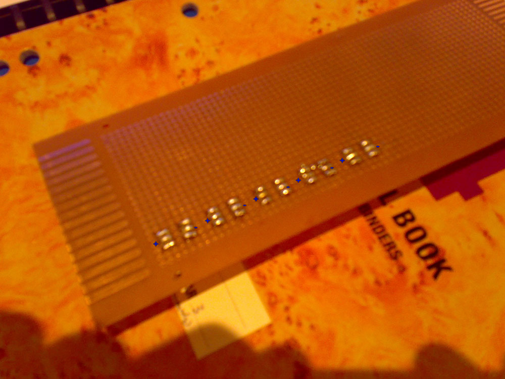
I am not very far into learning electronics yet but I ordered 20 of these buttons for a midibox SID synth I am making (the buttons are fantastic! and so cheap!) I was wondering if anyone could tell me how they are wired though? I want to set them up so the buttons are always lit regardless of being pressed or not being pressed. I have taken a photograph with my camera phone of the back of the veroboard I have soldered them to…Its horrid picture quality but hopefully you get the idea of how I have laid them out. I have marked in the orientation of the LEDs for clarity. Could anyone identify which of the remaining 4 connectors are the ones for the actual button function? I would have thought only 2 of the 4 were actually used to send the button current? Also…what kind of current do I run to the leds? do I need a resistor or are they good to go? Sorry, I know these questions are worded badly…this really isnt my forte!
Any advice anyone can give is greatly appreciated 
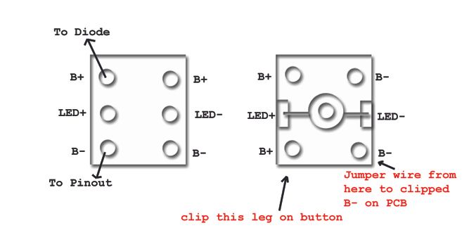
if these are the monome like all in one button red then the legs will have a + and a - on each side so it will look like this
it should be like the first button in this image
how are you controlling the board? the led current can be done a few ways but if you driving them direct from digital I/O ports then you will need a resistor. if they are going through some sort of IC, like a MAX7221/MAX7219 then the resistor is put on the legs of the IC.
what is your total project like? you use an arduino? or anothe microcontroller?
ok, once again my lingo probably isnt right, but the leds will just be running straight off the power…nothing controlling them (when its on…they are on…in other words). What kind of resistors will I need?
The project is written up on this website:
ucapps.de/midibox_sid.html
Also, i assume you only need to wire up one of each of the + and - for the button to function?
The diagram you drew…is that when looking at the underside of the button? or top down?
thanks 
that midibox looks interesting for sure!
as for the buttons, yes only one leg of + and - is required to make it work.
its best to just test continuity of the button when pressed. if you have a digital multi-meter with continuity checker, attach the probes to 2 contact points and see if it goes through. that way you can be sure your wiring it correctly.
on the resistors, if they are always on as you say, then you need to know what voltage is coming in and plan on a forward voltage of 2v for Red and green and 3.5 to 4v for Blue and white. also the output is needed so go for around 20ma for regular leds. you can calculate the resistor needed here
Thanks! Yea, its great fun as soon as its finished I think I would like to make one of the monome-style devices on here! looks awesome!
Apparently these LEDs will be supplied with 5v…a guy on the midibox forums suggested a 1k resistor. would you also agree with this?
while i dont know much yet about the setup of this box, 1k on 5 volts would be like an LED with .5v forward voltage and 5ma output so it doesnt sound right. but again, i do not yet know the complete specifics as to how its all hooked up.
when I did the math, I worked out it would need to be roughly 150…does that sound more realistic? I dont know much about resistors…but for the longjevity of the LEDs would it be an idea to get a resistor somewhere between 200 and 300 instead?
yea you could use a 150, and even go a little higher and be fine. 220s and 330s are pretty common/easier to find and you should be ok with those.
are you putting a resistor on each LED or do you have some sort of multiplexing IC that things are being hooked up to that requires a resistor for running all the LED’s?
Each LED will be having its’ own resistor. After talking more to the guy on the midibox forums, I am thinking I will be going 1k resistors…I really need these LEDs to suck up as little juice as possible…and they dont really need to be bright…as long as I can see them I will be happy. with 1k resistors and 5v they will light up yea? just not super bright…
just hooked up a button with a 330 ohm and a 1k ohm side by side and there is a negligible difference. i would have taken a picture of them but you just could tell to much. I guess only if you were looking would you see that the 1k is dimmer. I think seeing it in daylight is out of the question but inside you should be fine to see it.
I ended up picking up some 560 ohm resistors…bit of a trade-off between brightness and mA used… will throw up some pics of the completed veroboard when I have a chance thanks for all the help guys!