Hello
I am making a camera trap system. I have a proto type using Arduino pro minis and a “break beam” infra red sensors,it works ok. Eventually I would like my system to comprise of more than one sensor which report any events to a master box near the camera which will control the filming process. This post relates to just a sensor unit not the master box.
I would like the sensors to report to the master box by radio but I have had a lot of trouble finding a reliable system. The RYLR998 is the best I have found so far and I plan to use them.
I want my sensor units to be small, a handful size, and waterproof. Up until recently I was struggling to see how I could fit all neccessary items into a smallish space, my component list was this:-
IR sensor - tiny
Arduino pro mini 3.3v
18650 battery
4056 charger unit
RYLR998
Then I learned of the Xiao MG24. This one can do all that the pro mini did but it also had a built in battery charger. It also has BLE which could be useful in my master box to talk to the camera,and its tiny!
I have ordered the stuff and I am waiting for it to arrive but in the mean time I am struggling with a power related problem. The MG24 needs 1.7-3.8v and the RYLR needs 2.3-3.6v, The 18650 is nominally 3.7 volts but I understand that a freshly charged cell could be 4.2v. If I take these values literally it seems that I cant just connect them all up and everything will be fine. The battery could be too high a voltage for either units.
I have seen several posts that seem to indicate that the MG24, at least, can cope with the higher voltage. I dont see how it couldn’t, it is made to accomodate 3.7v lithium cells and everyone knows that these can output a higher voltage that there nominal 3.7v. I am suprised that Seeed do not explain this situation better.
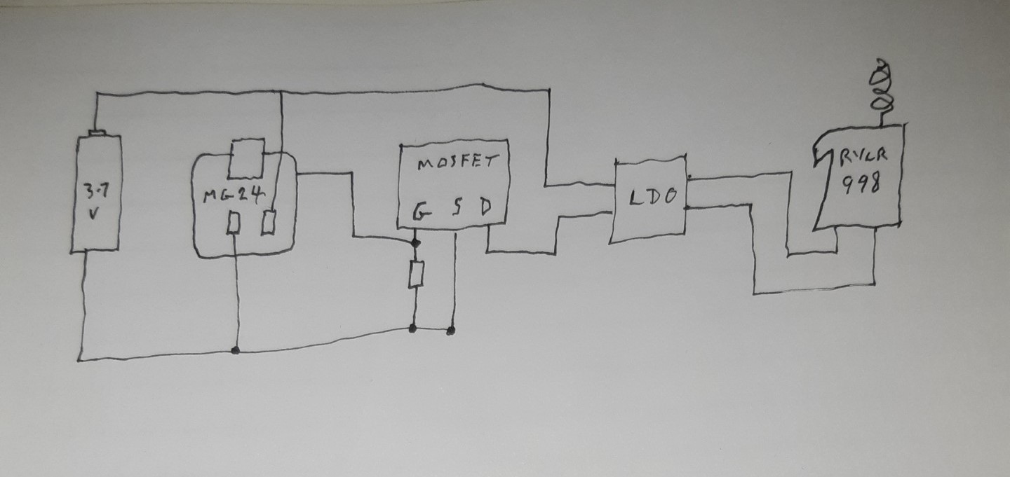
The RYLR, I dont know about, maybe it cannot tolerate more than the 3.6V. I am considering a circuit as shown in my very poor sketch and I would appreciate some advice on whether it may work. My thinking is that the MG24 can tolerate the 4.2v but the RYLR cannot. The TC1262 can reduce the voltage for the RYLR in normal use. When not being used a physical switch could be used to put the MG24 into deep sleep and the mosfet would be turned off thus dissconnecting the RYLR. The cell could then be charged via the USB socket.
A 3.3V 600mA step-down converter is implemented in the XIAO_MG24.
If you are not using the MG24 radio, I believe you can supply 3.3V 140mA to the RYLR998 from the 3V3 pin.
If you are using NMOS FETs, you need to select the ones with the lowest possible GateThresholdVoltage to ensure that they can be turned on with XIAO’s HIGH=3.3V.
So I know the Mg24 guys won’t like it but that is a NO_GO IMO.
Don’t even get me started, closed development system, proprietary Secure bootloader for DFU updates. MCUboot is well known and supported. that is just one point in future proofing future product design.
Why not this? The Nrf52840 Xiao also has a battery charger and It can also supply the Lower regulated and on-board LDO required for 3.3Vdc supply for the RYLR998 LORA Transceiver.
Given this Battery Voltage vs. Module Requirements:
A fully charged LiPo battery can measure around 4.2 V, which is above the typical operating voltage of many LoRa transceiver modules like the RYLR998 (which usually expect a regulated 3.3 V supply). You’ll need to ensure that your design includes proper voltage regulation (for example, a low-dropout regulator or DC‑DC converter) so that the transceiver sees a stable 3.3 V, regardless of the battery’s charge level.
Power Supply Stability:
The MG24 board and the transceiver module must be supplied with clean, stable power. This means that in addition to regulation, proper decoupling (with capacitors) is needed to handle the transient current draws that occur during transmission.
Battery Voltage Measurement:
As mentioned earlier, the MG24’s built-in battery voltage measurement in the available BSPs may not be very accurate below around 3.5 V. If you plan to monitor battery voltage (for example, to know when to charge), you might need an external PMIC or voltage measurement circuit that can accurately track the entire battery discharge curve—from 4.2 V down to, say, 3.0 V.
Hi there,
If I may…
The MG24’s radio is designed for 2.4 GHz protocols like Zigbee, Thread, Bluetooth, and other proprietary 2.4 GHz schemes—it does not natively support LoRa modulation.
LoRa uses a proprietary chirp spread spectrum modulation (developed by Semtech) that requires dedicated hardware (like the SX127x or SX126x series) to generate and decode those chirps. If you need LoRa capabilities, you’d typically integrate a dedicated LoRa transceiver alongside the MG24 rather than expecting the MG24’s radio to handle LoRa.
Pretty sure you can add the same radio slab to the MG24 BTW, they have several types, UART, & SPI and B2B versions. Of just the Lora Radio, also External 3db-6db antennas
so rang is not an issue , 20km as tested AFAIK.
HTH
GL PJ
I maintain way more powerful in Radio class but also Lowest power on battery and in deep sleep. (and costs less) $9 vs $12 (rylr998)
And Yes Welcome here…
I would go this route and save yourself some time and Learning curve, Review carefully the posts and issue’s with MG24 and off- shoots. Many have come this way,
here is why The main differences come down to integration, the LoRa transceiver chip, and the overall capabilities:
RYLR998:
This is a standalone LoRa transceiver module, typically based on the Semtech SX127x family.
It provides LoRa connectivity on its own and is meant to be interfaced with an external microcontroller.
You choose the microcontroller and build your design around that external transceiver.
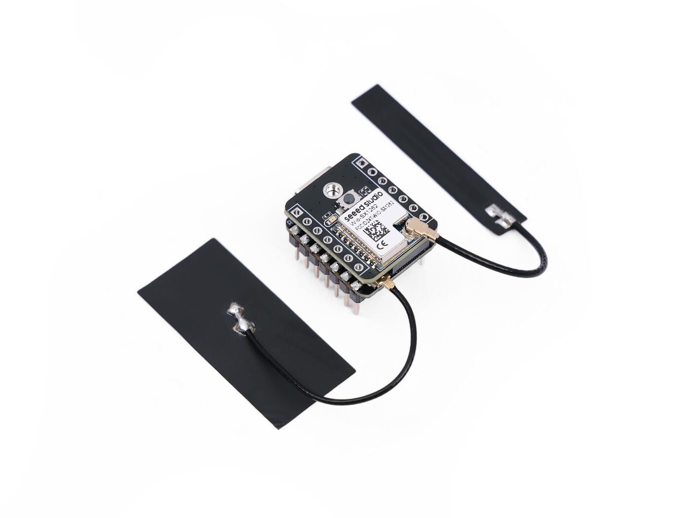
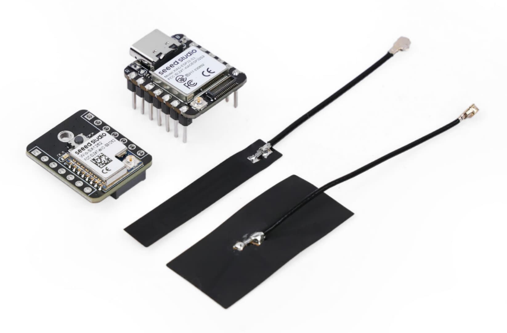
Wio SX1262 with XIAO ESP32S3:
This board integrates a newer Semtech SX1262 LoRa transceiver with an ESP32S3 microcontroller on the same board.
The SX1262 offers improved sensitivity and lower power consumption compared to the older SX127x series found in modules like the RYLR998.
With the built-in ESP32S3, you also gain WiFi, BLE, and the full power of a modern MCU—making development easier and the overall design more compact and integrated.
In short, if you need a simple LoRa transceiver and already have a microcontroller in your design, the RYLR998 might be sufficient. However, if you’re looking for an integrated solution that combines a high-performance MCU with a next-generation LoRa chip (along with extra connectivity options), then the Wio SX1262 with XIAO ESP32S3 offers a more modern, compact, and versatile platform.
Some background info.
I am making this system for a freind who makes wildlife movies. A typical filming scenario could be an area of say 25meter radius with 4 sensors placed at key positions. 2 might be placed at where the animals usualy enter from and the other 2 would be at the filming location. A signal from the distant sensors will start the filming, signals from the other sensors will keep the filming going. The sensors talk to the master box by LoRa and the master box talks to the camera by BLE.
For the sensor comms I have tried Bluetooth, BLE and other systems but have found the range very poor. I dont really need a very long range, 50m would be fine, but I will not always have line of site and this seems to be an issue.
The master box will talk to the camera by BLE so it will be placed withing 2 or 3 meters of the camera.
Thanks for the info, makes a lot more sense now. I did a similar project some time ago and range was also in the 10’s of meters but with to a maximum of 300m due to potential transmission degradation during bad weather.
I used Zigbee for the sensors and a Zigbee/BLE controller. LoRa bandwidth was not sufficient as the sensors had quite a bit of information to track, including RF tags.
Since you are not using the radio on the MG24, power consumption should be quite low (<20mA) and the on board 3V3 regulator should be sufficient to power your LoRa module.
I did add solar charging as the sensors were quite remote. If I did the project again I would use the new microwave sensors however and better power supply.
Apologies, I have not yet mastered the way of replying to a specific person within a string of posts so this may not come out as I wanted. I am trying to address this one to PJ Glasso.
The Wio SSX1262 with XIAO ESP32S3 look interesting and I take your point about an integrated solution. However, the height of this stack may be a problem for me. Could the modules be mounted side by side rather than stacked?
(sorry for bad English) My Xiao is connected to a 3.7v battery via BAT pin directly, I already try with VTC6 and 200mah lipo battery, the Xiao did not turning on, I’m connecting it with 2 OLED and it just turning on if connected to 5v (type c) supply, pls help me I wanna use it as portable mini game
And Welcome here…
No such thing as Bad English…
Do you have a “While Serial” in Setup function? If so then It waits until the serial port is connected before continuing.
Comment that out and flash again.
HTH
GL PJ
In Arduino, “while(Serial)” means a loop that will continue to run until the serial communication is established and ready to receive or send data; essentially, it waits for the serial port to be active before proceeding with the code within the loop.