Hello,
I was wondering why digitalWrite(LED_RED, !digitalRead(LED_RED)) does nothing (useful).
But after spending some time i found out that (LEDR, !digitalRead(LEDR)) does the job.
Last time this problem was discussed 22 ![]()
Hello,
I was wondering why digitalWrite(LED_RED, !digitalRead(LED_RED)) does nothing (useful).
But after spending some time i found out that (LEDR, !digitalRead(LEDR)) does the job.
Last time this problem was discussed 22 ![]()
Hi Putzlicht,
I assume LED_RED is set as an output pin in order to flash the LED, before digitalRead, don’t you need to set LED_RED an input pin?
Last time this problem was discussed 22
What is 22? Is it a link?
codes like LED_RED and BUILTIN are defined in the source code and setup code, config files for each board. It is not necessarily interchangable, for example some hardware may have a red led, some may have an amber led, some may have no built-in led at all.
This is why it make make a difference if you have the wrong board selected at compile time
It is a simple more human readable way to alow the user to not need to know which pin they are controling, but if the variable is not setup, the compiler has no idea what you are saying you say digitalWrite(LED_RED) it sees digitalWrite(Ham_Sandwitch)
just as if you say digitalWrite(LED_RED) to an amber led, the processor cannot control the color of the led
I hope that is understandable…
#ifndef Pins_Arduino_h
#define Pins_Arduino_h

#include <stdint.h>

#define USB_VID 0x2886
#define USB_PID 0x0056

static const uint8_t LED_BUILTIN = 21;
#define BUILTIN_LED  LED_BUILTIN // backward compatibility
#define LED_BUILTIN LED_BUILTIN  // allow testing #ifdef LED_BUILTIN

static const uint8_t TX = 43;
static const uint8_t RX = 44;

static const uint8_t SDA = 5;
static const uint8_t SCL = 6;

static const uint8_t SS   = 44;
static const uint8_t MOSI = 9;
static const uint8_t MISO = 8;
static const uint8_t SCK  = 7;

static const uint8_t A0 = 1;
static const uint8_t A1 = 2;
static const uint8_t A2 = 3;
static const uint8_t A3 = 4;
static const uint8_t A4 = 5;
static const uint8_t A5 = 6;
static const uint8_t A8 = 7;
static const uint8_t A9 = 8;
static const uint8_t A10 = 9;

static const uint8_t D0 = 1;
static const uint8_t D1 = 2;
static const uint8_t D2 = 3;
static const uint8_t D3 = 4;
static const uint8_t D4 = 5;
static const uint8_t D5 = 6;
static const uint8_t D6 = 43;
static const uint8_t D7 = 44;
static const uint8_t D8 = 7;
static const uint8_t D9 = 8;
static const uint8_t D10 = 9;

static const uint8_t T1 = 1;
static const uint8_t T2 = 2;
static const uint8_t T3 = 3;
static const uint8_t T4 = 4;
static const uint8_t T5 = 5;
static const uint8_t T6 = 6;
static const uint8_t T7 = 7;
static const uint8_t T8 = 8;
static const uint8_t T9 = 9;

#endif /* Pins_Arduino_h */
This is the definition file for the XIAO ESP32S3
It may be differend for ESP32 Dev Board, etc
For example, note that LED_BUILTIN is defined as pin 21
also BUILTIN_LED is also defined for backward compatibility, (Quite Literally) so you can use either word, or just say pin 21
so
digitalWrite(LED_BUILTIN) works
digitalWrite(BUILTIN_LED) works
and
digitalWrite(21) works
BUT
digitalWrite(RED_LED) DOES NOT WORK
If you add the code
static const uint8_t RED_LED = 21;
then the command will work by toggling pin 21, but has no control of the color
If the led was an RGB Led, and the red leg was on pin 21, THEN the led would also be red…
assuming the other two legs are off…
i am assuming this question was discussed in the forum in 2022…
Hi msfujino,
your assumption is’nt wrong ![]() But if we define a digital pin as output, and that’s the default, digitalRead() returns the state of the underlying port register. We don’t read a real logic level from a physical input.
But if we define a digital pin as output, and that’s the default, digitalRead() returns the state of the underlying port register. We don’t read a real logic level from a physical input.
This works out of the box on an Arduino NANO and also on a XIAO BLE:
void setup() {}
void loop() {
digitalWrite(LED_BUILTIN, !digitalRead(LED_BUILTIN));
delay(1000);
}
Please see post 8 of the following link:
“Xiao BLE Sense RGB LED pin definition - #8 by PJ_Glasso”
I have tried digitalWrite(PIN, LOW) and digitalWrite(PIN, HIGH), I can turn on/off the LEDs on all pin definitions.
Your question is that there are LED port registers that are not readable in 2.9.2?
Hi cgwaltney,
thanks for your explanations!
The point is that there are two completely different cores for the XIAO BLE.
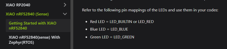
If we suggest that the non mbed enabled core is our reference, the following led definitions are correct:
https://wiki.seeedstudio.com/XIAO_BLE/#playing-with-the-built-in-3-in-one-led:
So this works as it should if we compile it under the non mbed enabled core:
void setup() {}
void loop() {
digitalWrite(LED_GREEN, !digitalRead(LED_GREEN));
delay(1000);
}
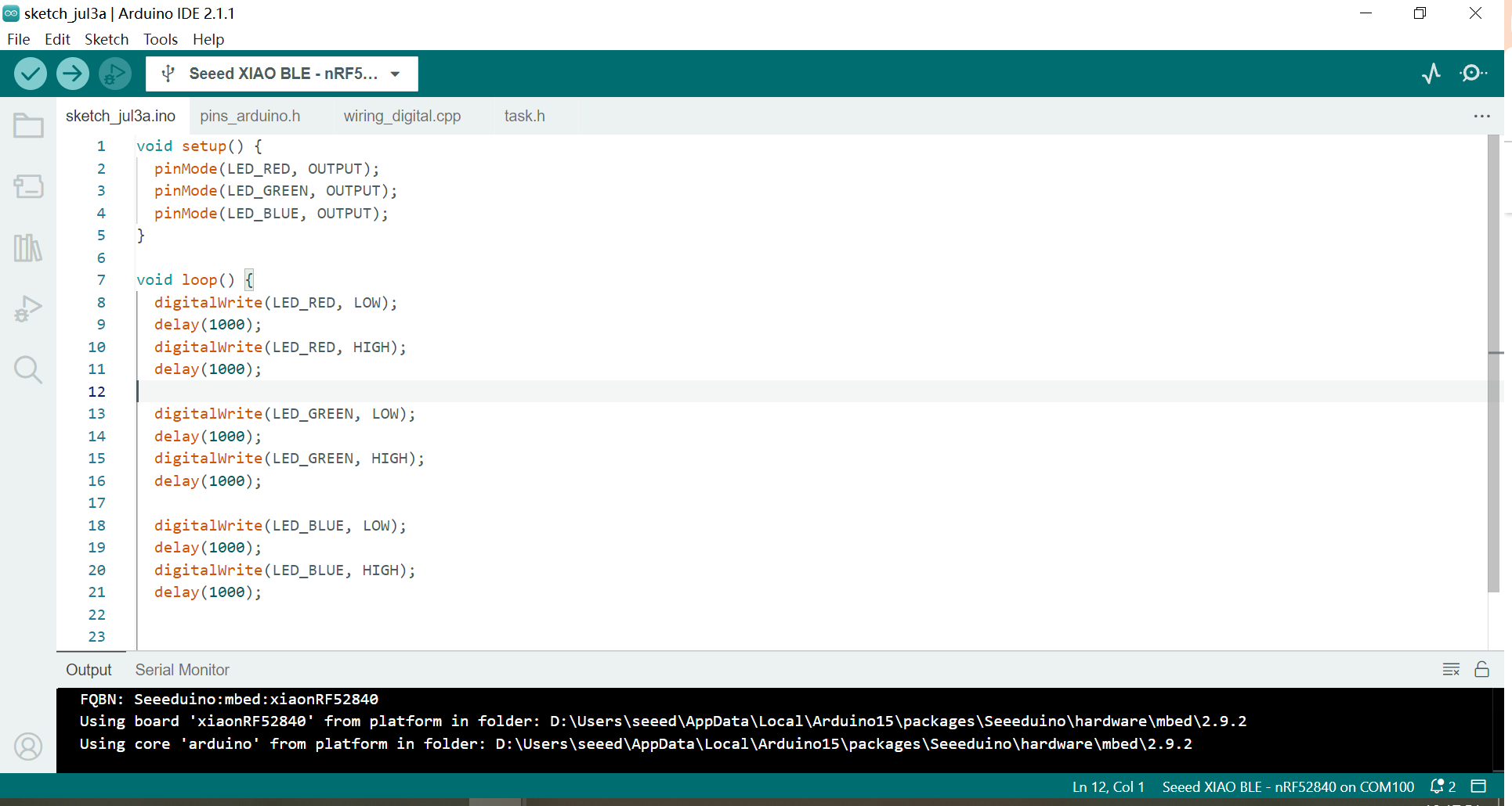
But if we compile it under the mbed enabled core it doesn’t work.
We have to use LEDG instead of LED_GREEN and so on.
In the end it’s not a big deal for an expirienced user to find out the working definitions.
But if you are new to microcontrollers, it can be very frustrating.
Seeed is stating at:
https://wiki.seeedstudio.com/XIAO_BLE/
- Both libraries support very well when it comes to the basic usage, such as LED, Digital, Analog, Serial, I2C, SPI.
But different definitions for the same hardware doesn’t mean “very well” to me.
And i don’t wanna talk about the use of different data types in the two cores for the pin definitions.
If no one complains, nothing changes ![]()
Nope. As I wrote:
I was wondering why digitalWrite(LED_RED, !digitalRead(LED_RED)) does nothing (useful).
But after spending some time i found out that (LEDR, !digitalRead(LEDR)) does the job.
LED_RED is stated as definition here:
https://wiki.seeedstudio.com/XIAO_BLE/#playing-with-the-built-in-3-in-one-led
But this does not work for the mbed anabled core!
Only LEDR works.
Best ![]()
“LED_RED” is not a problem on mbed 2.9.2 in the following code.
Your question is that there are LED port registers that are not readable in 2.9.2?
//----------------------------------------------------------------------------------------------
//BSP : Seeed nRF52 mbed-enabled Borads 2.9.2
//Board : Seeed nRF52 mbed-enabled Borads / Seeed XIAO BLE Sense - nRF52840
//2023/07/04 @msfujino
//----------------------------------------------------------------------------------------------

// define 1
//#define R P0_26
//#define G P0_30
//#define B P0_6

// define 2
//#define R 12
//#define G 13
//#define B 14

// define 3
//#define R LEDR   // LEDR or LED_BUILTIN or PIN_LED
//#define G LEDG
//#define B LEDB

// define 4
#define R LED_RED
#define G LED_GREEN
#define B LED_BLUE

void setup() {
  Serial.begin(115200);
//  while(!Serial);

  pinMode(R, OUTPUT);
  pinMode(G, OUTPUT);
  pinMode(B, OUTPUT);
}

void loop() {
  Serial.println("LED TEST");

  digitalWrite(R, LOW);
  delay(500);
  digitalWrite(R, HIGH);
  delay(500);
  digitalWrite(G, LOW);
  delay(500);
  digitalWrite(G, HIGH);
  delay(500);
  digitalWrite(B, LOW);
  delay(500);
  digitalWrite(B, HIGH);
  delay(1000);

}
its important to realize the mbed enabled core is a whole different animal its kinda like saying arduino is like raspberry pi… it is not so end of subject… im still waiting for all the xiao code to work correctly
Hi msfujino,
in my opinion this kind of workaround should not be used.
Your code works.
But this for example works not:
const int R = LED_RED;
I guess the definitions are const chars, not integers.
LED_RED just should work for booth cores. It’s not “my job” to write precompiler instructions just to decide on which core I am actually are ![]()
And now let’s get back to work and do something useful…
Unfortunately I am not a software expert so I don’t really understand what you are saying. I need to learn a little more.
For me, it is enough to know that I can turn the LED on and off by writing in this way.
No, it’s not so complicated as it looks. I am also just coding for fun.
All what I want is a unique definition for the led pins on booth cores.
Because booth cores addressing exactly the same board.
Banana means banana and apple means apple.
Doesn’t matter where you are.
But here LED_RED means the red led but not LEDR.
And LEDR means the red led but not LED_RED.
If you are new to microcontrollers and you buy a XIAO BLE Sense for 15 to 20$ and digitalWrite() to LED_RED does not work as described on GetStarted from SeeedStudio
because you are on the wrong core, does it worth the money then?
trust me there are bigger fish to fry… you can just write a few lines of code and have bannana turn on an amber led… no biggie if you want some coding fun, try re-writing the whole XIAO NRF52 codebase to actually work at all
In my mind, I have been thinking that “mbed and non mbed are completely different things even if the hardware is the same”.
I guess that’s the limitation of holiday programmers.