Hello,
can anybody say what’s the highes voltage for channel C and channel D with an 1x probe?
Somone says no more than 3 volts?!?!?! Is this right?
Thanks for reply.
Ciao rj.2001
Hello,
can anybody say what’s the highes voltage for channel C and channel D with an 1x probe?
Somone says no more than 3 volts?!?!?! Is this right?
Thanks for reply.
Ciao rj.2001
maximal working voltage for resistors in input CD limiter - 100v
assume any logic level
According to viewtopic.php?f=22&t=1978&p=6953 the inputs of the FPGA are 3.6V or 4.0V max and according to the schematics 2.6 they are protected with 5V zener diodes (which are analog components which won’t even block everything above 5V).
So the limit seems to be less than 5V. It would be nice if somebody of squeeezestudio could comment.
Patrick
in FPGA present internal diodes for ESD protection. They, along with limiting resistors, form the “first line” of defense against voltages above Vss.
4 volt limit from datasheet relates to the sources with no current limit. In our case, the current limiting resistor.
Do I understand you right: the 11k resistor (together with the 4V zener in the FPGA) limit the current to about 1V/11=0.1mA through the zener in the FPGA and this zener can withstand this current without damage during unlimited time?
Patrick
Yes, but usually it is not protected with zener. Commonly used standard diode to Vss rail.
I’m still worried about two facts:
I cannot find any mention of internal protection diodes in the datasheet. I would like to know the maximum current for them, because often it is quite low (less than 1mA):
kapsi.fi/~jpa/stuff/other/iCE65Datasheet.pdf
kapsi.fi/~jpa/stuff/other/iCE65L … asheet.pdf
The 11kohm resistors are before the 5V zeners, so if the FPGA input protection diodes clamp earlier then the 5V zeners have no effect. Therefore an input voltage of 15 V would already feed 1mA @ 5 volts to the FPGA.
A detailed description of the ESD protection circuits found in the documentation is quite rare. But these circuits are always present. Otherwise, in the production process will be too large percentage of damaged components.
Typical maximum continuous current for components like MCU and FPGA - 5-20mA.
Ok,
please let me know If I right:
On ChC and ChD I can connect a voltage higher than 3 volts, but not higher than 100 volts (80Volts max according to the data sheet).
So, 12V-DC-levels should be ok. Sure any logic voltage level are recommended.
Right?
Thanks.
Ciao
I measured the input current on my Channel D:
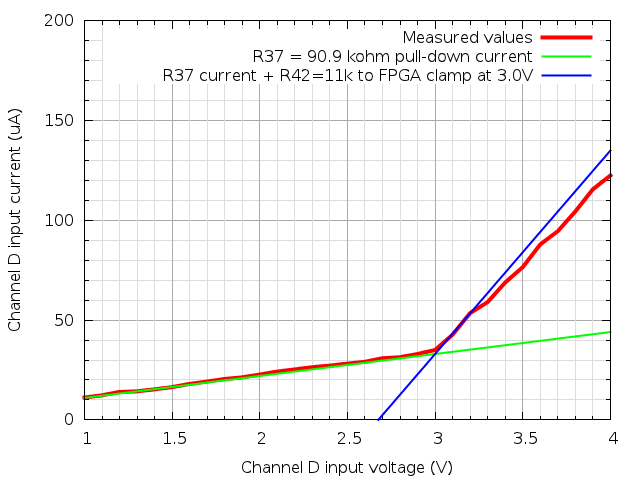
There is indeed some protection diode in the FPGA that kicks in at 3V (I think it is clamping to the 2.8V rail).
With more precise measurements, it should be possible to calculate at which point the voltage at the FPGA input pin exceeds 3.6V. When the current rises, the input protection diode will have a higher forward voltage drop, and it should be visible in the graph as the red curve deviating from the blue. Unfortunately, in my measurements, most of the deviation is caused by the voltage drop in my multimeter and so it is impossible to say anything precise from that. I wish I had uCurrent 