I’m having an issue with my Wio Terminal where there is significant temperature-dependent clock drift (very roughly 2500 ppm). At room temperature I don’t see an issue, but at ~ 45 F I get about 0.5 s of drift over a 200 s test. I’ve replicated this on two different units.
What could I be missing here?
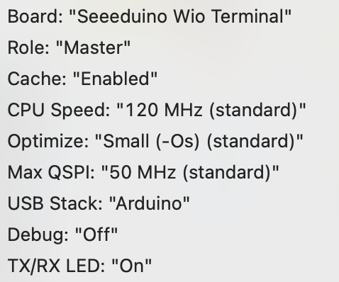
Setup:
Code written in Arduino IDE, uses millis() and toggles LED state whenever value crosses a 1000 ms interval.
Arduino 1.8.19, Seeed SAMD Boards version 1.8.3
A bit more information — I used a soldering iron at ~ 150 F to individually heat a few components on the board. Neither oscillator being heated caused an issue, however heating the processor itself did cause it. Anyone know if it’s possible for it to be defaulting to the processor’s built-in oscillator?
Well for future reference I think I’ve (or rather my friend) solved this. The Seeeduino board support package configures the Wio terminal to use the internal RC oscillator (low accuracy) instead of one of the external crystal oscillators. I don’t know whether this was intentional or not, but here’s a fix for people who have need for better timekeeping than the RC oscillator allows for.
Insert the following code into the setup function. It will override the clock configuration that’s normally contained in the startup.c file from the BSP (Seeeduino/hardware/samd/<version>/cores/arduino/startup.c)
  // Set up external 32 MHz crystal oscillator
  OSCCTRL->XOSCCTRL[1].reg =
    OSCCTRL_XOSCCTRL_STARTUP(9) | // 15.6 ms stabilization time - kinda arbitrary
    OSCCTRL_XOSCCTRL_ENALC |    // Auto loop control - saves a little power
    OSCCTRL_XOSCCTRL_IMULT(6) | // Current multiplier, per datasheet recommendation
    OSCCTRL_XOSCCTRL_IPTAT(3) | // Current reference, per datasheet recommendation
    OSCCTRL_XOSCCTRL_XTALEN |   // *Crystal* oscillator, using XOUT as well as XIN
    OSCCTRL_XOSCCTRL_ENABLE;    // Enable the oscillator

  // Wait for 32 MHz oscillator to be stable and ready to be used
  while ( ! OSCCTRL->STATUS.bit.XOSCRDY1 );

  // GCLK5 is supposed to output 1 MHz. This then feeds DPLL0 -> GCLK0 -> CPU core clock.
  // From startup.c, GCLK5 was sourcing from (open-loop) DFLL48M at approx 48 MHz and dividing by 48.
  // We'll change that to source from XOSC1 (which now provides 32 MHz) and to divide by 32.
  GCLK->GENCTRL[5].reg =
    GCLK_GENCTRL_SRC(GCLK_GENCTRL_SRC_XOSC1_Val) | GCLK_GENCTRL_GENEN | GCLK_GENCTRL_DIV(32u);

  // Wait for register synchronization
  while ( GCLK->SYNCBUSY.bit.GENCTRL5 );

  // Note, DFLL48M is still open-loop and the 48 MHz GCLK1 ("USB and stuff")
  // and the 12 MHz GCLK4 ("DAC") are still derived from that.