[size=200]Lipsyncing Robot Face and Number Display Using Rainbowduino [/size]
[size=150]Introduction[/size]
I’m sure not that everyone needs a lipsyncing robot face that can also display numbers, but this is also a tutorial on how to use the Rainbowduino with discrete LEDs rather than the RGB matrix display. It is simple enough to build in an afternoon and the parts (not including the Rainbowduino) cost about $15.
[size=150]The project[/size]
My 11-year-old son Sam was building a robot for the Robocup Junior Dance competition. In this competition kids design and build robots that dance in time to a song. The song he was using was“Robots”, by Flight of the Conchords. The song features a “binary solo” so some sort of big number display was a must, and he wanted to have a nice glowing robot face as well. Later on he got the idea to lipsync the robot’s mouth to parts of the song.
He was building the robot using Lego Mindstorms NXT, and we knew the NXT brick did not have enough outputs (without expensive expansion boards anyway) to drive LEDs, so we went looking for a better display controller.
There are a lot of interesting Arduino-related project materials on instructables.com and the Arduino site, and we learned about multiplexing and even Charlieplexing. We tried a multiplexed display using an Arduino Duemilanove and this design, but it wasn’t really bright enough. We were looking at adding some power driver chips to the Arduino outputs.
Then we found the Rainbowduino and realized it could do all this in one package. It could drive up to 192 LEDs at high power. It also had firmware already developed that could display images and text displayed on a matrix, which meant Sam could get on with writing the display program without having to get too deep into shift registers and interrupt service routines. Also it was quite cheap, and very small.
[size=150]Parts list:[/size]
LEDs
I bought some cheap high-intensity LEDs from DealExtreme. You can use just about any LEDs though. There are presets for adjusting the brightness on the Rainbowduino board if you need them.
Circuit board
Sam needed to build this quickly so we chose protoboard. It is not as tidy as a proper PCB but it is quick and easy and looks didn’t really matter for this project, in fact the klunkier it looked the better.
Connectors
I bought some 0.1mm header connectors to plug in to the headers on the Rainbowduino. You can get these from Seeedstudio or most electronics suppliers. Sam soldered some rainbow wire directly on to the connectors.
UARTSB
The Seeedstudio UARTSBboard was used to program the Rainbowduino.
Circuit
Here’s the circuit diagram:
[size=150]Building the display board[/size]
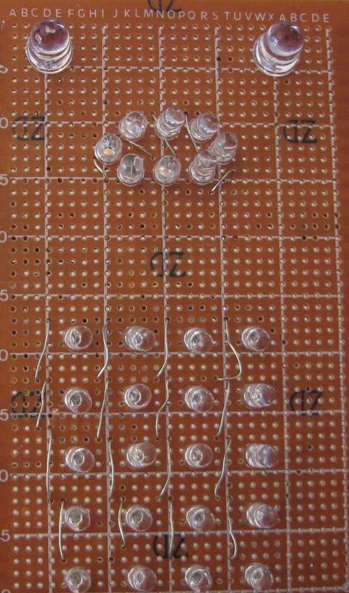
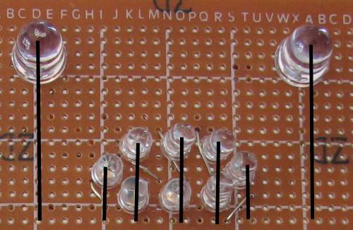
Arrange your LEDs on the protoboard the way you want them, with the long leads (anodes) at the bottom. Here is the arrangement Sam used:
The face is connected up in three rows:
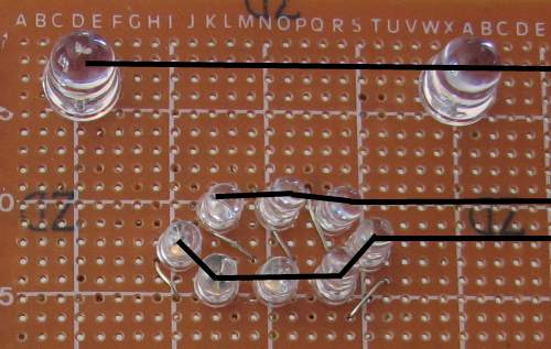
And seven columns:
To connect up the LEDs, bend all the anodes to the right so they are touching each other, and solder them together along each row.
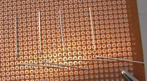
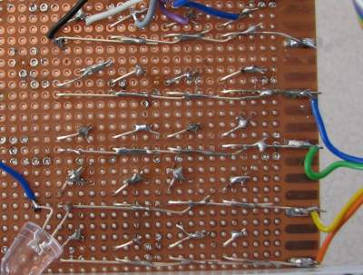
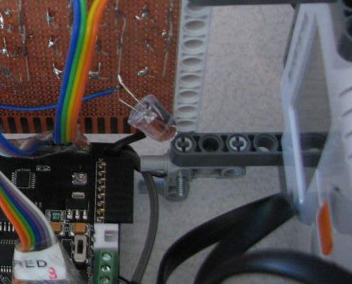
Insert link wires to connect up each column of cathodes (the short leads). Trim the leads up. The end result should look something like this, only much tidier of course! The extra LED in this picture is a “fridge light” LED which will be described later.
[size=150]Connecting to the Rainbowduino[/size]
The rows (anodes) are connected to the VCC pins and the columns (cathodes) on the 4x5 matrix are connected to the Green pins, and the columns on the face are connected to the Red pins. This makes it a little easier to control the face and the 4x5 matrix independently.
The left-most column number matches "Red/“Blue”/“Green” pin 8, and the rightmost column is pin 1. The top row (eyes) matches VCC pin 1, bottom row is pin 8. Refer to the circuit diagram to get everything hooked up. As long as there are no shorts you can’t really damage anything if you get it wrong, the lights just won’t come on.
[size=150]Fridge light[/size]
Finally it was hard to see the NXT display inside the robot when the robot’s body was in place, so he added a “fridge light” inside the body:
[size=150]Input[/size]
To kick off the Rainbowduino program at the start of the song, Sam wired up the analog input (Rainbowduino pin ADC6) to the Mindstorms touch sensor. I put a tutorial for doing this Here on instructables.com. He even added a self-test routine that will trigger if you hold the touch sensor down for three seconds.
[size=150]Power[/size]
We opened up the NXT brick and wired the Rainbowduino power directly to the battery connectors on the PCB, so we didn’t need a separate battery pack for the Rainbowduino. This turned out to be a bad idea: when the robot really got going, the motors were under heavy load and the LEDs were full on, so the battery voltage from the six AA batteries in the NXT sometimes fell low enough to make the Rainbowduino reset. He switched to alkaline batteries to get higher supply voltage and used nearly-new batteries for each run, which seemed to avoid the problem, but it would have been safer to use a separate battery.
[size=150]Mounting it on the robot[/size]
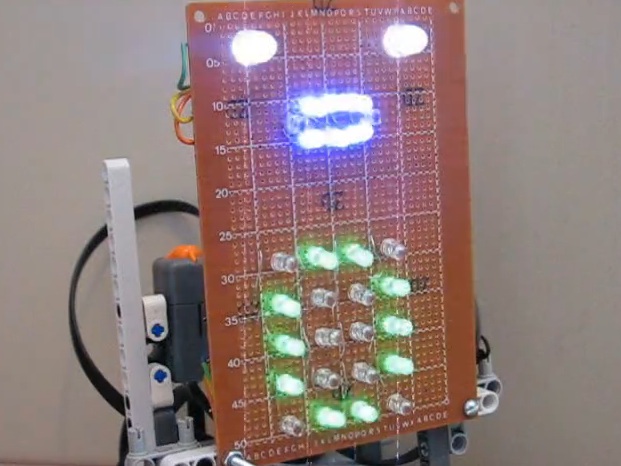
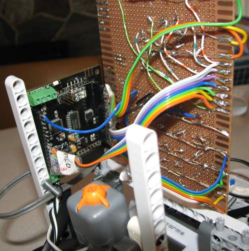
Here it is all hooked up to the Rainbowduino and mounted on the robot:
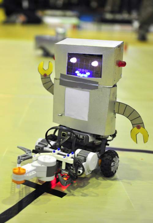
And here is a front view with the robot body on (photo courtesy of the Robocup organisation). The screen over the matrix was just paper. It makes the display look much better by diffusing the LEDs a little.
[size=150]Software[/size]
Software files
Here’s the software code for the project: Our_Rainbow_CMD_V2_0.zip (8.47 KB). It compiles with the standard Arduino IDE.
Firmware
We started with the standard Rainbowduino sample sketch. I added some simple functions to call the Rainbowduino driver functions:
// Show a character on the green and red LEDs (matrix and face) void showGreenAndRedChar(char c);
// Show a character on the “red” LEDs (face) using the Rainbowduino driver code
void showRedChar(char c);
// turn on all LEDs with brightness (0-15) set for each colour
void showColourRGB(byte red, byte green, byte blue);
// Show one of the animation frames from Prefabnicatel in data.c
void showFrame(int frame);
Displaying numbers
The first step was to get the numbers 0 and 1 displaying on the matrix. The original firmware was programmed for an 8x8 matrix and this number matrix 4x5, so Sam redefined the bitmaps for the numbers. These are in the file data.c.
He started off by writing the matrix out in binary, with the “1” characters representing pixels that would be on:
// B01100000,
// B10010000,
// B10010000,
// B10010000,
// B01100000
If you squint at the pattern made by the 1’s, it looks a bit like a “0”. There are extra zeros on the right-hand side because that’s the way the matrix is wired up: the left column of the matrix corresponds to the highest bit in the number.
Then he converted the binary numbers to hex and entered them in the character bitmap for “0” in data.c. The top three rows were initially blank, we added the bits for the face in later.
He fired this up, added showGreenAndRedChar(‘0’) to the code and it worked first time!
Mouth shapes
The lipsync idea came up after the display board had been built. With hindsight it would have been better to build a mouth with more LEDs to get a more pronounced difference between mouth shapes.
In the character definition Sam added the top three rows for the eyes and mouth on ‘0’:
//01000001 eyes
//00011100 top mouth
//00011100 bottom mouth
And gave ‘1’ a smiling shaped mouth (because the left and right LEDs in the bottom row are higher):
//01000001 eyes
//00000000 top of mouth
//00111110 bottom of mouth
So the mouth shape when displaying ‘0’ and ‘1’ was the right shape for the lipsyncing effect, so it looked a little like the robot was saying ‘0’ and ‘1’. And for a bit of extra lipsyncing to “Finally, robotic beings rule the world” at the start of the song, an extra ‘2’ with all the mouth LEDs on:
//01000001 eyes
//00011100 top of mouth
//00111110
The lipsyncing and the binary solo were driven by arrays using timing derived by loading the song into a wave editor (Audacity) and timing each syllable down to the millisecond, then assigning one of these mouth shapes to it. You can see the code for this in the functions “finallyRoboticBeings()” and “binarySolo()”.
Random display
The next feature was what Sam described as a “crazy disco light display” for the “Robo Boogie” section of the song. He wanted it to just display random patterns but the code to generate that was a bit beyond him and it only needed to last about 15 seconds, so he just made up the animation sequence bitmaps using a spreadsheet that generated two random hex characters from 0 to F in each cell. When pasted into the “Prefabnicatel” array in the data.c file, this makes dots go on and off at random. He then tweaked the bits for the eyes so they flashed on and off together.
Fade out
Finally the lights needed to all come on and then “fade out” as the robot pretends to “run out of batteries” at the end of the song. This is in the function “finalFace()”.
Demo
Here’s a video of the robot running its self-test routine where it cycles through all the displays. Please excuse the video noise, I had the camera a bit close to the LEDs.
[size=150]http://vimeo.com/6922284[/size]
[size=150]The result[/size]
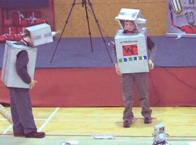
It all came together and worked really well. He had to do a lot of tweaking to get the timing right and synced in with the song. Here it is performing in the Robocup Junior competition:
[size=150]http://vimeo.com/6587391[/size]
This is cut together from two different performances because the second performance went slightly wrong at the end, but had a better lighting display. If you would like to see an unedited runthrough with slightly less fancy lighting it is on YouTube Here.