Is BSP the printed circuit? I ade one with a pushbutton connected to a pull-up input. Output Is a pulse of 1 10 2 ms, every 8 ms.
It seems that calculations where only integers are involved, are O.K.
But to read the acceleration sensors I have to convert and scale floating values:
Hi there,
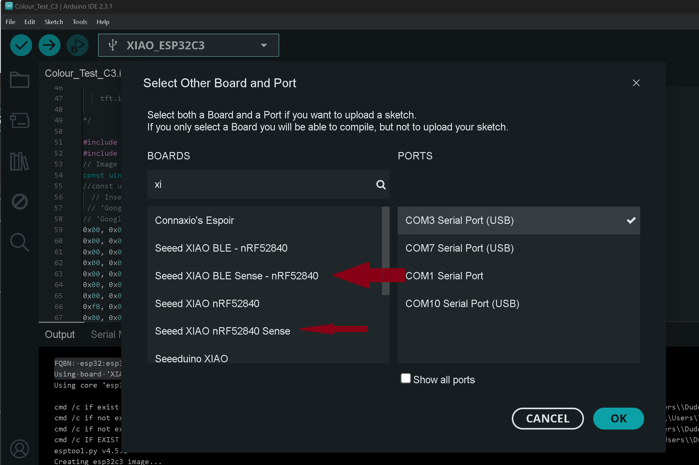
No it’s the board support Package you pick when you select the Board in the arduino IDE
There are two, Depending on which one is Selected and used in the first line of the compiler output after the Fully Qualified Board Name…FQBN
here is the Xiao ESP32C3 , using BSP @ 2.0.8
FQBN: esp32:esp32:XIAO_ESP32C3
Using board 'XIAO_ESP32C3' from platform in folder: C:\Users\Dude\AppData\Local\Arduino15\packages\esp32\hardware\esp32\2.0.8
Bellow is the Xiao Nrf52840 series.see two choices, the first one is this, mbed 2.9.2
FQBN: Seeeduino:mbed:xiaonRF52840Sense
Using board 'xiaonRF52840Sense' from platform in folder: C:\Users\Dude\AppData\Local\Arduino15\packages\Seeeduino\hardware\mbed\2.9.2
the second one is the non-mbed 1.1.8
FQBN: Seeeduino:nrf52:xiaonRF52840Sense
Using board 'xiaonRF52840Sense' from platform in folder: C:\Users\Dude\AppData\Local\Arduino15\packages\Seeeduino\hardware\nrf52\1.1.8
On my Mac mini, the only BSP I can find for my nRF52840 Sense. is the Seed nRF52 mbed enabled Boards. Deinstalled all others, but it did not help.
The float values can be between. -4,000 g and +4,000 g. No documentation available on how the I2c measurements are made.
But maybe you have another idea.
also give a look at the data sheet , you can round the readings also to help conversion.
you can use a Kalman Filter also to give pitch and Yaw from the raw readings.
HTH
GL PJ
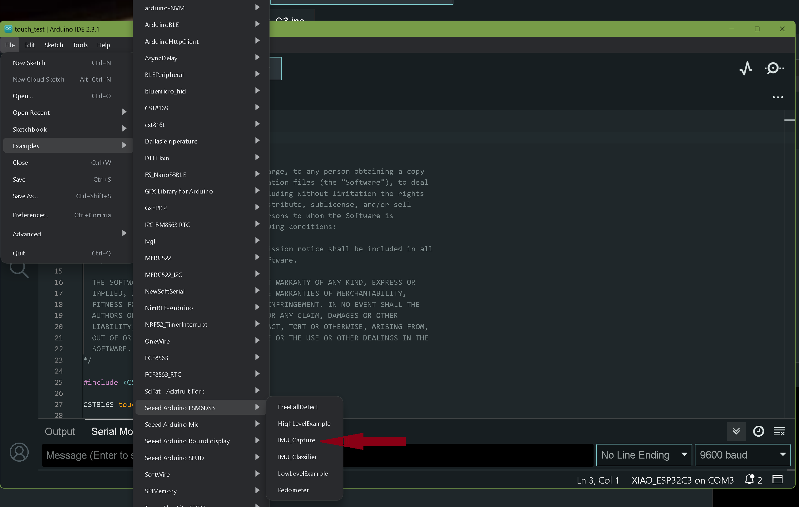
in IMU Capture the same float readings are used as in the high level examples.
I like the Low level approach, because with one call I get integer values for x and y
One g is 4000. In my application, the max value expected is 3 g, so 12000, OK as integer.
But the problem remains, time issues are corrupted when the acceleration calls have been made.
I will try to isolate the sensor call in a separate function. But that will have to wait until next week, I have to take care of my grandson…
Hi there,
Yes Good to know the Low level gets it done, You have any other devices connected? Those pins are for I2C communication with those devices. You can also enable a time stamp that is in the IMU presented with the readings. So maybe look there if high precision for timing is needed.
Read over the Data Sheet for the LSM6DS3 during the down time and check out all the things it does as well.
Look at this thread, by Msfujino. There’s a lot in there but well documented.
HTH
GL PJ
ps. I’m having fun with my Nephews, 12,10, 7… I showed them the 3D printer and we printed some darth vaders, storm trooper and spiderman head,etc. I think 1 of the three is destin to be an engineer.
Stil no progress.
Changed the output pin from 4 to 0. Pin 5 not used any more.
Measured acceleration values are perfect, but delays and mills() vary wildly, as soon as the Bluetooth software is used.
The bluetooth communication works very nice, but it messes up all time issues.
Am I really the first person to use BT and IMU at the same time?
I hope I do not have to throw away the Xiao Senses…
Rads,
Hi there,
Without seeing the actual Code in Question, Perhaps you need an additional LIB installed for RTC or interrupts.?
are you using the builtin TimeStamp function?
HTH
GL PJ
is there anything to control the timers? In the past, in Assembler you had complete control of the 2 Microchip timers…
There is no difference between using multiple delayMicroseconds and using millis(). (unsigned long).
Just to clarify: I have to generate a servo pulse with a frequency of 125 Hz (8 ms for one complete pulse). The HIGH duration is calculated when the servo signal is LOW. During this LOW time, I measure the x and y values two times (3 ms separated), calculate the averages, and calculate the duration of the next HIGH duration.
So, I cannot use the Arduino servo library.
The problem is, that the calculations are OK, but on the scope I see that the HIGH and LOW durations now and then are exceeded for one to two ms, but not constantly…
Hi there,
Without Seeing the code, I can’t offer much help.
Yes, There is an Interrupts Library and a Timer Library both for Nrf52840 , I don’t have links but you can search here for the examples folks have posted. Sounds like that is what you need.
HTH
GL PJ
Yes, the example blink_print in the timer library is interesting. But I do not understand the toggle principle.
My timer needs pulse of 1 to 2 ms. Then, in the LOW time, the duration of the next pulse is calculated.
Then, after 8 ms since the beginning of the first pulse, everything happens again.
Could you lease look at that sketch, and give me an indication for the solution?
Kind regards,
Hi there,
LOL, man I vaguely remember some Fortran77 back in the 80"s ? Punch cards too. WOW
The Nrf52840 has Several timers and the PWM’s You can use either.
to achieve the outcome, Check out how Arduino generates Pulses link
Basically set the pulse length, attach an Interrupt, In the ISR reset the timer value start the duty cycle timer with interrupt and rinse and repeat.
like this one, it’s also applicable to Xiao.
HTH
GL PJ
I’ll look at the blink_print time permitting and make some comments.
Thanks for the suggestions,
The TimerOne library looked perfect, but it seems not to work with my Xiao Sense, The examples will not compile…
Tried also to change the frequency of the Servo library. Was not able to change the Refresh Interval to 8000 instead of 20000… Still stuck…
Hi there,
Have you tried the other BSP? In the board selection Pick the second one. What is the BSP that is NOT compiling? Look at compiler output and see which it is.?
HTH
GL PJ