LED polarity trouble on nRF52840

I’m trying to blink the onboard LED of Xiao BLE (not sense) 10 ms each 10 s. So:

#include <Adafruit_TinyUSB.h> // For Serial.print()

void setup()
{
  
  Serial.begin(115200);
  delay(10000);
  
  // LED initialization   
  pinMode(LED_BUILTIN, OUTPUT);
   
  Serial.println("Setup finished");
}

void loop()
{
  digitalWrite(LED_BUILTIN, HIGH);
  delay(10);
  Serial.println("Blink");
  digitalWrite(LED_BUILTIN, LOW);
  delay(10000);
}

Indeed, the red LED is always up and only switch off for a fraction of second.

In opposite, no problem with Adafruit nRF52840 Feather and ItsyBitsy. I just have a flash each 10 s.

If I switch LOW and HIGH in my sketch, Seeed board is blinking as expected.

Did I missed something?

Aduino IDE 1.8.19. “Seeed nRF52 Boards” version 1.1.1. Seeed XIAO nRF52840.

BTW, even the very simple exemple sketch don’t behave as expected:

/*
  Blink

  https://www.arduino.cc/en/Tutorial/BuiltInExamples/Blink
*/

// the setup function runs once when you press reset or power the board
void setup() {
  // initialize digital pin LED_BUILTIN as an output.
  pinMode(LED_BUILTIN, OUTPUT);
}

// the loop function runs over and over again forever
void loop() {
  digitalWrite(LED_BUILTIN, HIGH);   // turn the LED on (HIGH is the voltage level)
  delay(1000);                       // wait for a second
  digitalWrite(LED_BUILTIN, LOW);    // turn the LED off by making the voltage LOW
  delay(10000);                       // wait for a second
}

i think i may have read that the led polarity is actually reversed on the xiao

Playing with the built-in 3-in-one LED

Seeed Studio XIAO nRF52840 (Sense) has an onboard 3-in-one LED which is user-programmable. Now you will learn how to control the RGB colors one-by-one using Arduino!

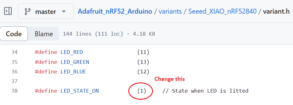
You first have to understand that the behavior of this LED is not as usual when controlled by the code. The LED turns ON when we give a LOW signal and it turns OFF when we give a HIGH signal. This is because this LED is controlled by a common anode and will light up only with a low-level signal.

An example code would be:

void setup() {  pinMode(LED_BUILTIN, OUTPUT);}void loop() {  digitalWrite(LED_BUILTIN, HIGH);   }

Here, even though HIGH is used, the LED will be OFF. You need to replace HIGH with LOW to turn ON the LED.

Refer to the following pin mappings of the LEDs and use them in your codes:

  • Red LED - LED_BUILTIN or LEDR
  • Green LED - LEDG
  • Blue LED - LEDB

Thanks for the explanation. So, this is not a bug but a functionality. :rofl:

Any compilation directive for this board?

So, I found SEEED_XIAO_NRF52840_H as directive:

void blink(const int blink_duration)
{
#ifndef _SEEED_XIAO_NRF52840_H_
  digitalWrite(LED_BUILTIN, HIGH);
#else
  digitalWrite(LED_BUILTIN, LOW);
#endif  
  delay(blink_duration);
#ifndef _SEEED_XIAO_NRF52840_H_
  digitalWrite(LED_BUILTIN, LOW);
#else
  digitalWrite(LED_BUILTIN, HIGH);
#endif  
}

But the next step is that I want to use BLE, with adafruit library. Indeed, the blue LED is acting opposite to expected. It is ON when BLE is deactivated and OFF when BLE is activated. Do I have to parse all Adafruit BLE code to add conditional directive as above? Any suggestion?

Bruefruit uses the blue LED for the connection indicator. Disable the connection indicator to use the blue LED.

Bluefruit.autoConnLed(false);

I think he is saying the led is indicating opposite because it is a common cathode rgb and
Apparently the adafruit must use a common anode

… so the adafruit code is envoking opposite

So he is asking if anyone knows where exactly in the code he can switch from high to low to
Make the BLE indicate correctly

Okay, I see what you mean.
I don’t know if this will help you, but you can invert it by doing the following.

bluefruit.cpp:952

void AdafruitBluefruit::_setConnLed (bool on_off)
{
  if (_led_conn)
  {
//    digitalWrite(LED_BLUE, on_off ? LED_STATE_ON : (1-LED_STATE_ON) );
    digitalWrite(LED_BLUE, !on_off ? LED_STATE_ON : (1-LED_STATE_ON) );
  }
}

Another suggestion is to modify the define of the variant.h file. This will then affect only a particular board:

1 Like

Thanks all for your answers. I may completely switch off the BT LED for the final project but I will start to have the expected behaviour following @hobbya suggestion.

did you say you tried changing the variants file and it worked?

I successfully tried changing the variant:

// LEDs
#define PIN_LED              LED_RED
#define LED_PWR              (PINS_COUNT)
#define PIN_NEOPIXEL         (PINS_COUNT)
#define NEOPIXEL_NUM         0

#define LED_BUILTIN          PIN_LED

#define LED_RED              11
#define LED_GREEN            13
#define LED_BLUE             12

#define LED_STATE_ON         0         // State when LED is litted

Now, the blue/BT is lighting as expected.

I took the opportunity to change my code:

void blink(const int blink_duration)
{
  digitalWrite(LED_BUILTIN, LED_STATE_ON);
  delay(blink_duration);
  digitalWrite(LED_BUILTIN, !LED_STATE_ON );
}

Thanks all for the help.