Ultimately this simple test project has proven the IOT2020 to be an effective product for access control and monitoring, future developments will include using a SQLite server on the IOT2020 to store card numbers and access records for communication with a cloud based system, and adding additional functionality such as lighting control and alarm integration.
IOT2020 Setup
Go to the Siemens website
Register an account
Download the example image
Extract the *.wic image
Copy to SD card
Personally I use Rufus to burn image files, use whichever tool you are comfortable with. Once the SD card is setup and installed into the IOT2020 we can power it up and begin configuring.
With the example image there are two ways to connect to the IoT2020, SSH or Serial Terminal. For both I recommend using PuTTY
Serial Setup
To use the serial terminal we must first connect a UART cable to the IOT2020, via header X14. Take note of the serial port created by the adapter. (In my case it was COM9). The following settings can be used to connect to the IoT2020 with PuTTY:
SSH
Connecting to the IoT2020 via SSH requires only an ethernet connection. The default IPv4 for the example image is 192.168.200.1/24 . Make sure your computer is configured within this range (eg 192.168.200.2 / 255.255.255.0).
The default login for the IoT2020 is ‘root’,
(Bonus) Setup Wifi
Once logged in, type ‘iot2000setup’ to access the network setup, make sure to set the address of the wireless adapter to ‘dhcp’ (unless you statically provision).
Install Node-Red
Enter the following commands to install Node-Red and the modules required; Warning: This can take a long to install, and warning messages will show as NPM needs to build some packages from source.
npm install -g --unsafe-perm node-red
mkdir .node-red
cd .node-red
npm install node-red-dashboard
npm install node-red-contrib-modbus
npm install galileo-io
Setup the X11 Serial Port
In order to use the onboard serial pins with node-red we first need to set them up, warning: this will prevent you from being able to upload arduino sketches via the USB mini port.
Whilst logged in as root, type ‘vi TTY0.setup.sh’, this will drop you into the default text editor ‘vi’, pressing ‘i’ will enter vi into edit mode, at this point copy & paste the following code:
#!/bin/sh
echo -n “28” > /sys/class/gpio/export
echo -n “32” > /sys/class/gpio/export
echo -n “45” > /sys/class/gpio/export
echo -n “out” > /sys/class/gpio/gpio28/direction
echo -n “0” > /sys/class/gpio/gpio28/value
echo -n “out” > /sys/class/gpio/gpio32/direction
echo -n “1” > /sys/class/gpio/gpio32/value
echo -n “out” > /sys/class/gpio/gpio45/direction
echo -n “1” > /sys/class/gpio/gpio45/value
Hit ‘Esc’ and enter ‘qw’ to save the file. Once the file is saved it must be made executable, by entering the following:
chmod +x TTY0.setup.sh
Now run the file to setup the serial port for use
./TTY0.setup.sh
Arduino Setup (Optional)
If you are using a Serial based RFID reader, then this step can be skipped. The setup is quite simple, using an Arduino nano we convert the Weigand-26 protocol of the RFID reader to the serial logic Node-Red can understand. Pins 0&1 on the Arduino should be connected to Pins 1&2 of the IoT2020 for the serial logic and Pins 2&3 of the Arduino need to be connected to the Clock (CLK) and Data lines of the reader.
The sketch at the bottom of this project can be used to test the functionality.
Webserver
Although the end-goal is to a Cloud solution like the Amazon AWS, we have to test locally first. The instance of this build I used the XAMPP package to quickly install a local webserver to my computer so that I could run a simple PHP script to test functionality. Essentially all thats happening here is Node-Red requesting the page from the server whilst also passing the card number via POST headers, then taking the returned string ‘answer’ which is in my case can either be 1 (let user in) or 0 (reject the user). My example code is listed below:
Using the Node-Red debug tab you can find your Card number and replace the one in the IF statement to grant access.
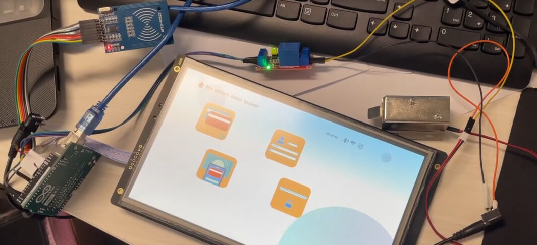
Using the Arduino relay shield
Install the relay shield into the IOT2020, and make sure to set the power option header to 5v. The relay shield offer 4 mechanical relays that are connected to Pins 4,7,8 and 12 of the board respectifully. In this instance we are only using 3 of them. The serial data lines will also need to pass through the shield board.
Regards,
Rachel Gomez