IC2 scanner reports no IC2 devices on ESP32-S3 + XIAO Expansion base

What am I doing wrong?

I can’t connect to any IC2 devices?

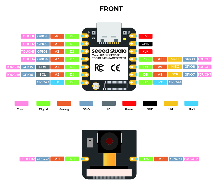
I’ve ESP32-S3 plugged into an XIAO Grove Shield Expansion Base, with any of:

Attached to the either of the 2 plugs marked (Gnd, 3v3, SDA 4, SCL 5). I’ve tried one or two devices connected to either or both ports.

I’m running code straight from

as shown below

// --------------------------------------
// i2c_scanner
//
// Version 1
//    This program (or code that looks like it)
//    can be found in many places.
//    For example on the Arduino.cc forum.
//    The original author is not know.
// Version 2, Juni 2012, Using Arduino 1.0.1
//     Adapted to be as simple as possible by Arduino.cc user Krodal
// Version 3, Feb 26  2013
//    V3 by louarnold
// Version 4, March 3, 2013, Using Arduino 1.0.3
//    by Arduino.cc user Krodal.
//    Changes by louarnold removed.
//    Scanning addresses changed from 0...127 to 1...119,
//    according to the i2c scanner by Nick Gammon
//    https://www.gammon.com.au/forum/?id=10896
// Version 5, March 28, 2013
//    As version 4, but address scans now to 127.
//    A sensor seems to use address 120.
// Version 6, November 27, 2015.
//    Added waiting for the Leonardo serial communication.
//
//
// This sketch tests the standard 7-bit addresses
// Devices with higher bit address might not be seen properly.
//

#include <Wire.h>

void setup()
{
    Wire.begin();

    Serial.begin(9600);
    while (!Serial)
        ; // Leonardo: wait for serial monitor
    Serial.println("\nI2C Scanner");
}

void loop()
{
    byte error, address;
    int nDevices;

    Serial.println("Scanning...");

    nDevices = 0;
    for (address = 1; address < 127; address++)
    {
        // The i2c_scanner uses the return value of
        // the Write.endTransmisstion to see if
        // a device did acknowledge to the address.
        Wire.beginTransmission(address);
        error = Wire.endTransmission();

        if (error == 0)
        {
            Serial.print("I2C device found at address 0x");
            if (address < 16)
                Serial.print("0");
            Serial.print(address, HEX);
            Serial.println("  !");

            nDevices++;
        }
        else if (error == 4)
        {
            Serial.print("Unknown error at address 0x");
            if (address < 16)
                Serial.print("0");
            Serial.println(address, HEX);
        }
    }
    if (nDevices == 0)
        Serial.println("No I2C devices found\n");
    else
        Serial.println("done\n");

    delay(5000); // wait 5 seconds for next scan
}

The code compiles & uploads & runs fine using Arduino IDE with latest libraries & boards, on Win10 Pro. The Serial monitor indicates it runs but finds no devices.

I’ve a bunch of other Seeed controllers & sensors to try if needed. I presume the Grove connecters that came with the sensors are fine to use. I presume the ESP32-S3 handles pull-up voltage on the IC2 pins OK. What else to check:

  • voltage form the ESP32-S3 matches that expected by the sensors
  • I need to remap the pin numbers somehow?
  • I need to use another library, not the standard WIRE one?

Any suggestions appreciated!

Enjoy your solstice…

the expansion board has IIC units the display and the RTC as you noted

Grove is the name of the cable and connector system… the 4 wire system is power and ground and 2 data wires… the data wires of each grove connector is different so you dont short circuit.

The exception being the IIC because it is a data bus… so you can have multiple units connected

So, on the grove expansion module the top 2 grove connectors are IIC BUT if you connect anything else into those connectors it may crash the bus

I am assuming you may have done this… otherwise an IIC scan should find the RTC and the display unless there is a problem in the code or the pin soldering

In similar form, this device also has 2 IIC grove connectors one in the lower left and one in the upper right…

I tried your code on my expansion board and it worked fine - results below.

I2C Scanner
Scanning...
I2C device found at address 0x3C  !
I2C device found at address 0x51  !
done

My BSP - 3.3.3.

No additional hardware (pullups). No changes to the Pin Numbering (standard SCL, SDA).

You could try Wire.begin with the SDA and SCL pin numbers and a lower speed?
Perhaps check the connections to the I2C bus are OK (oscilloscope?).

Finally, (more advanced and shouldn’t be necessary), run the application using the built in JTAG debugger.

Edit> What ESP32-S3 are you using?
Another Edit> All works with XIAO-ESP32-S3, SAMD21 and ESP32-DevKit-C and my custom board (ESP32-S3-WROOM-1U-N16R8).
Yet another edit> Try using “Core Debug Level = Verbose” to try detect any conflicts?

1 Like

Gosh, I’m embarrassed. None of the 3 devices I tested with actually had IC2 interfaces! Once I tried one with that interface it did work fine. The most obvious things….

2 Likes

Thanks for the update :slight_smile:

Dear all,

I am struggling with I2C sensors as well. I am not able to get a single on detected while scanning.

I use a ESP32S3 on the Grove base for XIAO. Non-I2C sensors like the DHT11 are working fine but neither the ATH20 nor the BMA400.

I replaced already the Grove base and cables but no success so far. Do you have any more ideas? The last thing would be the ESP32 itself…

Cheers Nick

[18:52:42.491][C][logger:261]: Logger:
[18:52:42.491][C][logger:261]: Max Level: DEBUG
[18:52:42.491][C][logger:261]: Initial Level: DEBUG
[18:52:42.492][C][logger:267]: Log Baud Rate: 115200
[18:52:42.492][C][logger:267]: Hardware UART: USB_SERIAL_JTAG
[18:52:42.492][C][logger:274]: Task Log Buffer Size: 768
[18:52:42.492][C][i2c.idf:090]: I2C Bus:
[18:52:42.492][C][i2c.idf:091]: SDA Pin: GPIO4
[18:52:42.492][C][i2c.idf:091]: SCL Pin: GPIO5
[18:52:42.492][C][i2c.idf:091]: Frequency: 100000 Hz
[18:52:42.493][C][i2c.idf:101]: Recovery: bus successfully recovered
[18:52:42.493][C][i2c.idf:111]: Results from bus scan:
[18:52:42.493][C][i2c.idf:113]: Found no devices

The main reasons why the I2C board doesn’t work with XIAO are:

  1. Incorrect connections
  2. Incorrect pin assignments for SCL and SDA in your sketch
  3. Your I2C board is operating at 5V instead of 3.3V

If you post a photo showing the connections, the sketch you’re using, and the I2C board’s documentation, the problem will likely be resolved quickly.

2 Likes

Yes I will bet he does not have the correct BSP chip pins selected

For the S3 it uses GPIO 5 & 6 for SPI Bus

to use pin # D4 and D5 in your code if using Arduino IDE you MUST select the target board as XIAO ESP32S3 otherwise all bets are off

1 Like

I tend to use the “actual” GPIO pin numbers for this. Alleviates BSP “issues”.
You mentioned using an ESP32-S3, is it the XIAO or some other module?

If XIAO, I2C are on GPIO pins 5 (SDA) and 6 (SCL).

If other module, you would need to ensure the correct wiring.

See…

1 Like

Thank you all so much. Yes, I have the XIAO ESP32S3.

@cgwaltney & @msfujino & @grobasoz I always used the wrong GPIO numbers. I was reading SDA4 and SCL4 on the Grove Base and thought that would map to GPIO4 and 5.

Now everything is working fine.

Thanks again!
Nick

2 Likes