I have a problem with the „Grove Beginner Kit for Arduino“.
The assembled board works fine, but after I broke out the modules, I figured out problems with the 3-Axis Accelerator and the OLED Display I2C Modules.
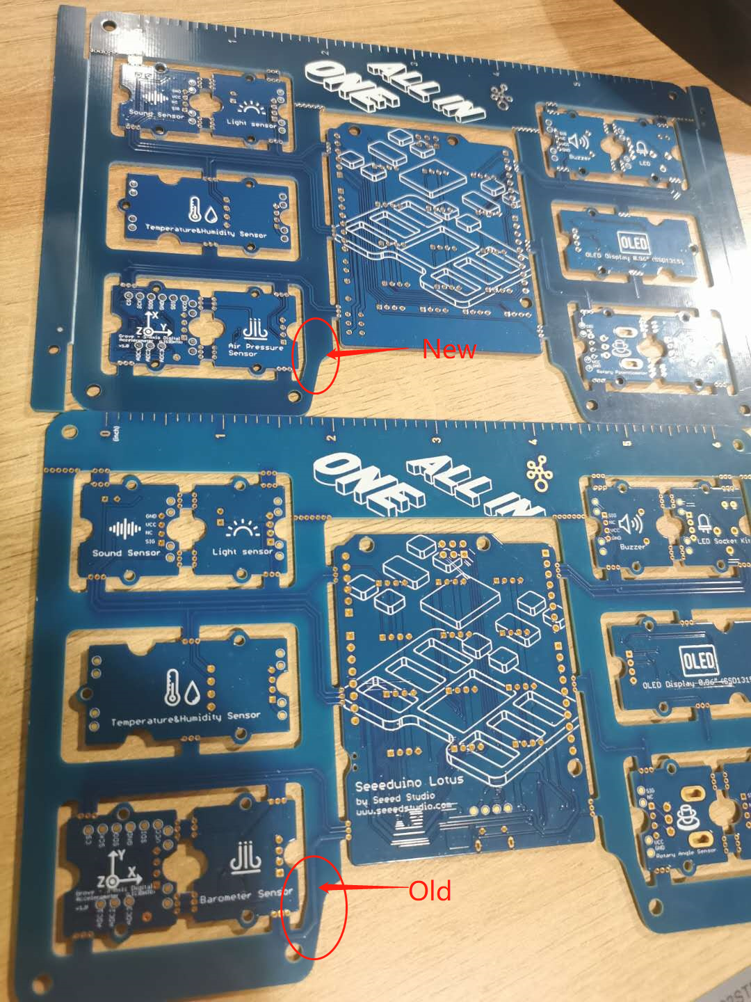
I have one original pre-assembled board and two disassembled boards, so I can compare the function.
All sketches work well on the pre-assemble board, but not with the disassembled parts.
The Problems:
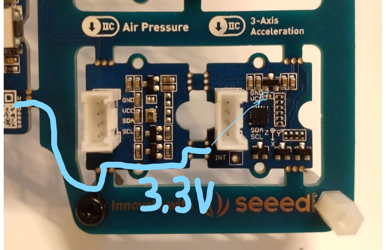
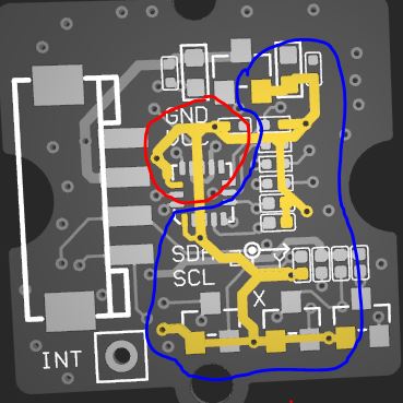
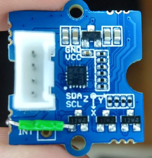
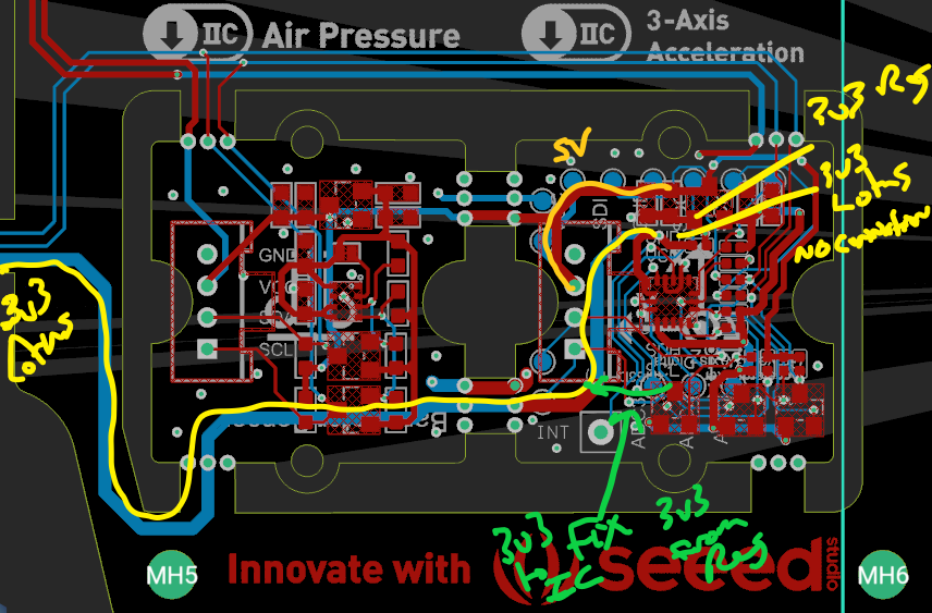
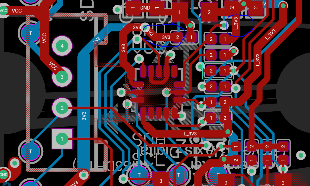
- 3-Axis Accelerator
I don’t get the 3-Axis Accelerator (LIS3DHTR) to work at all after I broke out the modules. (Both two disassembled modules, so I don’t think I destroyed the boards…)
I always get the error message “LIS3DHTR didn’t connect.” from the sketch.
I also figured out that there are two versions of the LIS3DHTR Library. One with
LIS3DHTR LIS(I2C_MODE);
initialisation and on with
LIS3DHTR LIS;
But this is not the problem. With both libs, it works on the assembled board and not with the single modules.
- OLED Display
The original sketch use HW I2C to init the modul
U8G2_SSD1306_128X64_NONAME_1_HW_I2C u8g2(U8G2_R2, /* reset=*/U8X8_PIN_NONE);
This did not work with the single module. The single module works only with SW I2C like
U8G2_SSD1306_128X64_NONAME_F_SW_I2C u8g2(U8G2_R0, /* clock=/ SCL, / data=/ SDA, / reset=*/ U8X8_PIN_NONE)
(The software I2C works on the pre-assembled board as well)
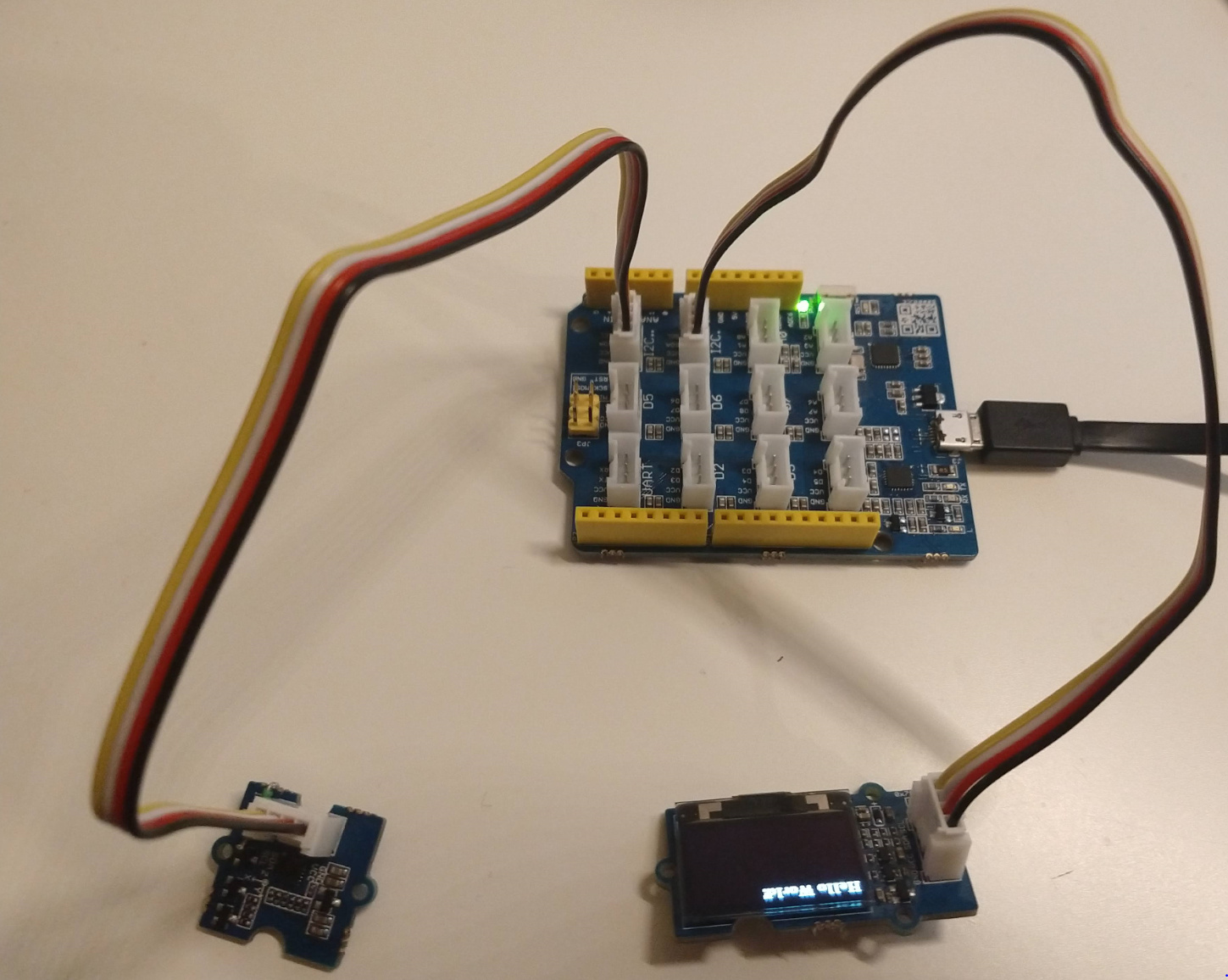
But now to the strange part. When I connect all I2C Bords (Accelerator, Barometer and the Display) I can use the HW I2C for the Display.
I use a Arduino Uno with Grove Shield (this has 3 I2C Ports), and uploaded the simple “Hello World” sketch for the Display with HW I2C.
When I only connect the Display, this doesn’t work, and the Display keeps black. But when I also connect the other I2C modules (without modifying the sketch) the Display works.
Has anyone an idea on one or both problems? Thanks!