I would like to connect Grove CAN (Serial) to Wio Terminal

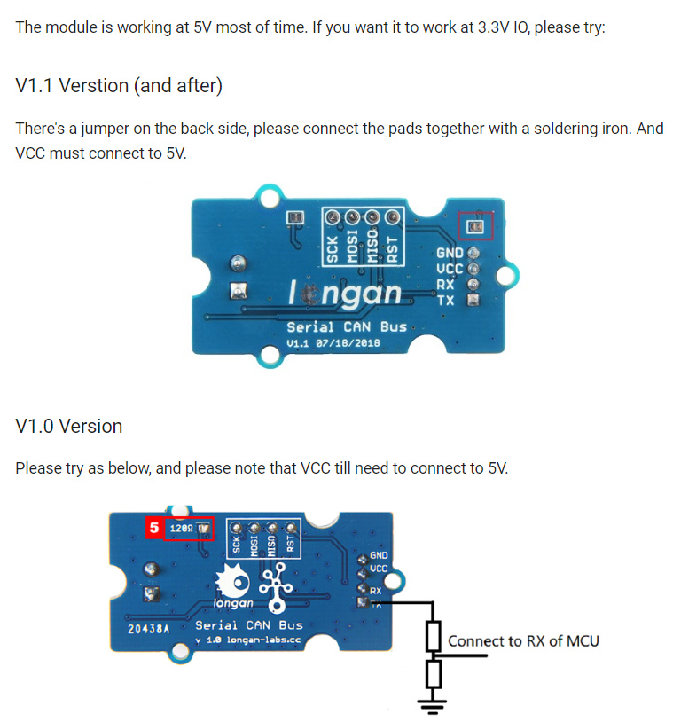
I firstly started from this structure

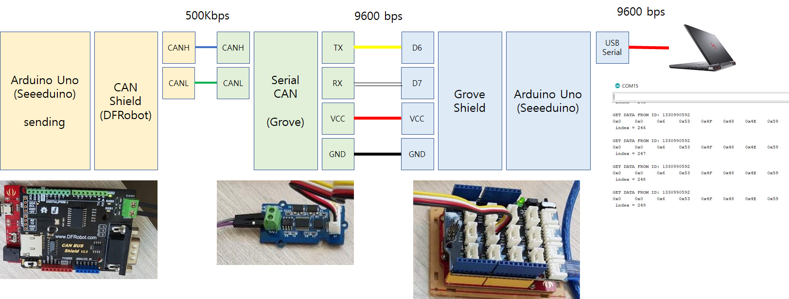
And I used SoftwareSerial function and the followings are the code used.

/ RECV EXAMPLE OF SERIAL CAN MODULE
// unsigned char recv(unsigned long *id, uchar *buf);
// SUPPORT: joney.sui@longan-labs.cc

#include <Serial_CAN_Module.h>
#include <SoftwareSerial.h>

Serial_CAN can;

static const int RXPin = 7, TXPin = 6;
static const uint32_t GPSBaud = 9600;

void setup()
{
Serial.begin(9600);
delay(1000);

can.begin(TXPin, RXPin, GPSBaud);      // tx, rx
Serial.println("begin");
//can.canRate(CAN_RATE_500);

}

unsigned long id = 0;
unsigned char dta[8];

// send(unsigned long id, byte ext, byte rtrBit, byte len, const byte *buf);
void loop()
{
delay(100);
static int index = 0;
index++;
if(index > 255) index = 0;
char Str[100];
sprintf(Str, " index = %d \n", index);
Serial.println(Str);

if(can.recv(&id, dta))
{
    Serial.print("GET DATA FROM ID: ");
    Serial.println(id);
    for(int i=0; i<8; i++)
    {
        Serial.print("0x");
        Serial.print(dta[i], HEX);
        Serial.print('\t');
    }
    Serial.println();
}
else
{
  Serial.println(" no data ");
}
delay(100);

}

// END FILE

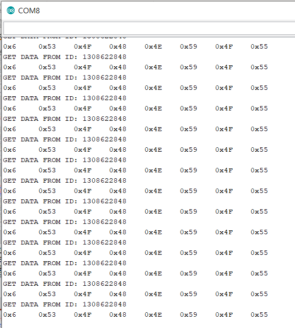
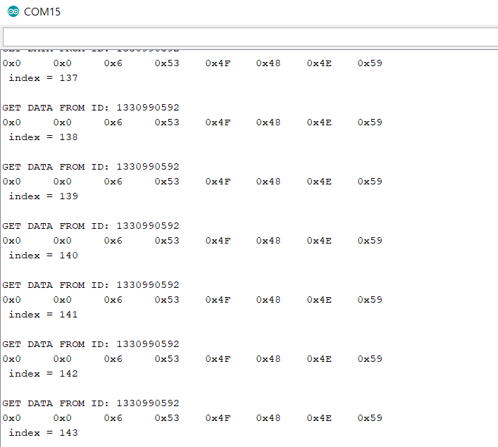
It runs like the following figure;

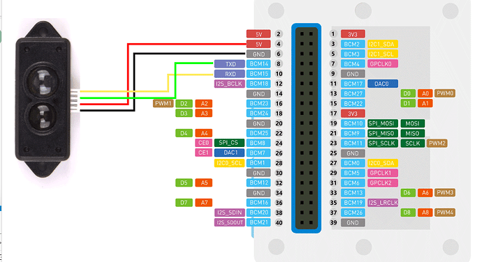
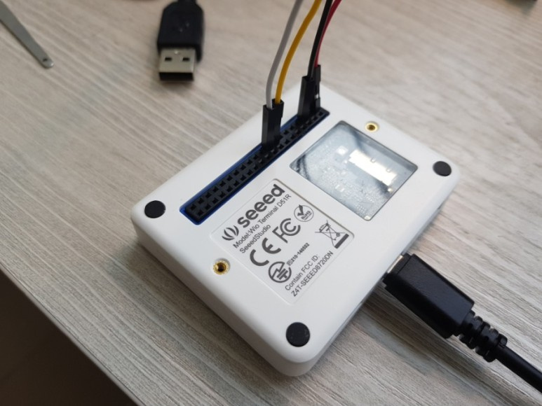
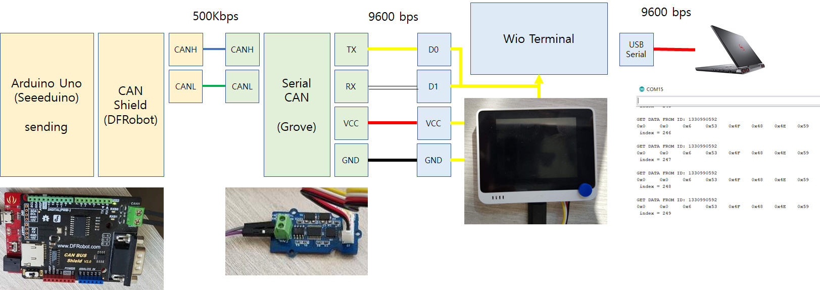
What I want to make is the wio terminal version of this CAN communication system.
like the followings figure

And I changed the one line like the followings;

static const int RXPin = 1, TXPin = 0;

it doesn’t work at all like the followings ;

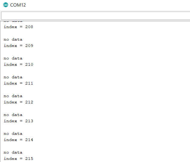
Maybe in order to use D0 and D1 and Softwareserial , there must be something more to do for me.

Please let me know about that.
Thanks.

Software Serial might be different here for TTL voltage compared to Uno. The best way to do it is to use Hardware serial on the 40-pin headers at the back of Wio Terminal

Thank you. I agreed with your opinion. At first I will try to check the voltages of the Grove connector of the Wio Terminal first. Thanks.

Yesterday I ordered digital multi-meter.
Today I got that and from now on I can measure the voltages.

At first, I checked that the VCC level in the Grove Shield of D6 is 5V (TTL)
However the VCC level of teh Grove connectors in Wio Terminal is 3.3V (not TTL level)

Is this the reason why I cannot use serial CAN IO. right?

I searched the document for the CAN module. I found that like the following link.

https://docs.longan-labs.cc/1030001/

it reads like as follows;

3.3 / 5V working voltage

hmm… what is the problem?
there is a comment about that.
maybe there must be a voltage shifter T.T

Is there any other way to resolve this problem? I am using v1.0 Serial Module.
If there is no way to do that. how about to change the CAN interface? Is there any candidate for Wio Terminal?

To work with 3.3V you will need to do the step as you listed for v1.0 verison. And what do you mean by change the CAN interface?

What I mean is to buy another CAN interface with VCC=3.3V and compatible with Wio Terminal.
In my thought, wio terminal is very very interesting and perfect arduino board which can be taught and used widely. If this device can be easily attached with some CAN interface, I would like to use this my standard device to monitor the CAN signals with Car experiment.

Yes, this should work in theory as for SAMD series boards like SAMD21 and SAMD51 have 3.3V for IOs instead of 5V for AVR series.

I saw this figure
image

and connect D2 and D3 like the following figure;

I just use the D2 (TX) and D3(RX) and software serial.

It works like the followings;

So the only problem is to 5V and 3.3V.
When I connect 5V instead of 3.3V VCC. both cases (TF Lidar and Serial C) work.
In my thought, the next version of the expansion pack. please let me get a small dip switch for 3.3V/5V switching.

When I connect D0 D1 instead of D2 D3, it also works.