How to test if a rainbowduino is failure?

I purchased a Rainbowduino recently in order to control several pieces of RGB LEDs . I connected 8 LEDs, which were verified in work order, to the rainbowduino. I believe the connection is right–the common anode to VCC and RGB to RGB, respectively. According to the description of the manual, an 8x8 LED matrix shoud be plugged and shine. I don’t have a LED matrix. But I expected these 8 LEDs should be turned on, at least some of them. Unfortunately, after I loaded a 9V power, nothing happened except the power light was up. In additin, I also tried to upload a sample sketch to test it. But I don’t have an UartSB either. So I used a normal arduino, connecting RX to RX, TX to TX, DTR to RTS, and also VCC and GND. The result is the same, all LEDs kept silent. Now I am totally confused. The power light of the rainbowduino is OK. It also blinked when I was uploading the sample sketch from an arduino. But no any RGB LED was lighted up. The most weird thing is that if I connected the VCC of the rainbowduino to 5V, arduino IDE reported information below while connecting to 3.3V was uploaded successfully.

avrdude: stk500_getsync(): not in sync: resp=0x00
avrdude: stk500_disable(): protocol error, expect=0x14, resp=0x51

I can confirm the connection is no problem because both the reset led and power led in the rainbow blinked when uploading. I also set a blank sketch to the main arduino in advance . Anyway, I have tried everything I can find but not even one led was on. Anyone know what’s wrong with my rainbowdino? Thanks a lot!
i had a similar issue with one of mine with the out of sync thing and i just had to redo the bootloader. I used a mega-isp and a seeeduino to write it, since then its been ok.

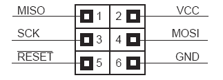
Thank you for help. Could you tell me how did you burn the bootloader? I downloaded the mega-isp and loaded it in the arduino IDE. Then I hooked 6 pins of the rainbowduino ISP up to an arduino according to the figure.

I selected “Arduino NG or older w/ ATmega168” in the board option and clicked Burn Bootloader with w/ AVR ISP. And then the java program had no response at all after a few minutes. Did I do something wrong? Thank you very much!
AVR-ISP.png

I didnt use the IDE to send it to the unit. I used avrdude. I did use the IDE to compile it.

Here is my method but if your not comfortable running the commands then you should get an actual programmer so the IDE will work.

Here is the main thread that is from

How did you wire your seeeduino up to the rainbowduino? Does it show below?

Seeeduino Rainbowduino
13<-----------SCK
12<-----------MISO
11<-----------MOSI
10<-----------RESET
5V<-----------VCC
GND<----------GND

I did follow your guide and get the result:

avrdude: safemode: lfuse changed! Was ff, and is now 0
Would you like this fuse to be changed back? [y/n] y
avrdude: stk500_cmd(): programmer is out of sync

Now I have to doubt there is hardware problem with the rainbowduino.
Thanks again!

when you plug in to the isp header does the rainbowduinos red light come on?

When i was hooking it up the first time, it felt like it was backwards on mine, like it was meant to have the header pointing down not up but i could be remembering wrong.

I dont have it in front of me know, but maybe tonight i can look at the wiring (if its still hooked up) or find a picture of how i had it.

you should be able to find the ground and power pins pretty easy, they make the red power led come on. after that, adjust your orientation of the other cables.

ok, on looking at mine, it seems to be wired right, just the silk screen ISP is upside down. the VCC is the right corner pin facing the power led.

if you have version 1.11 the ISP label is on the side that GND and RESET is on
if you have version 1.0 the ISP is on the side MISO and VCC is on

are you geting a power indicator when you plug them in?

do you get power indicator when you power the external green plugs or the JST pins or the uart pins?

I great appreciate for your patience. It seemed a bit of progress tonight. I finally rewrite the bootloader. The previous error occured because I selected to change back fuse during command line–an ashamed mistake. I will put the detail below since I am not quite confident–the last line of the first command report:“avrdude: stk500_disable(): protocol error, expect=0x14, resp=0x00” . I don’t know why.

Hi ernestyu,
Sorry for response tardy.

We burn the Arduino dicemila bootloader in Rainbowduino Atmega168.
Which device did you upload the sketch to Rainbowduino?

Thanks
Albert

The arduino clone device I am using is called ‘Roboduino RoMeo’. Here is the manual:

I’ve checked out the board and confirm it has an ATmega168-20AU, just the same as the rainbowduion. Last week I ruined the bootloader of the RoMeo when I tried to rewrite the rainbowduion through the former. It took me the whole weekend to save it. Fortunately I got one answer from

and finally succeeded. I also find it can make the arduion become an AVR-Writer. So I wrote a dicemila bootloader to the rainbowduion. I thought the method should be able to work because the RTS Led of the rainbowduion kept lighting when I was burning it. However, problem seems to go back to the original–I cannot even turn on a single LED. Indeed I didn’t make it work since I’ve received it two weeks ago. Further more, I hooked up the rainbowduion to the RoMeo by the method from

.

When I tried to upload a sketch, the arduino IDE always reported :

The strange thing is if I connected VCC of the rainbowduino to 3.3V rather than 5V in the RoMeo board, it responded no error. I’ve tested the VCC output of the rainbowduino following the post

.
It didn’t work in my case, just no led be lit. Since I have neither a LED matrix nor a UartSB, I can not directly determine where the problem lies in. So, any suggestion? Thank you very much!