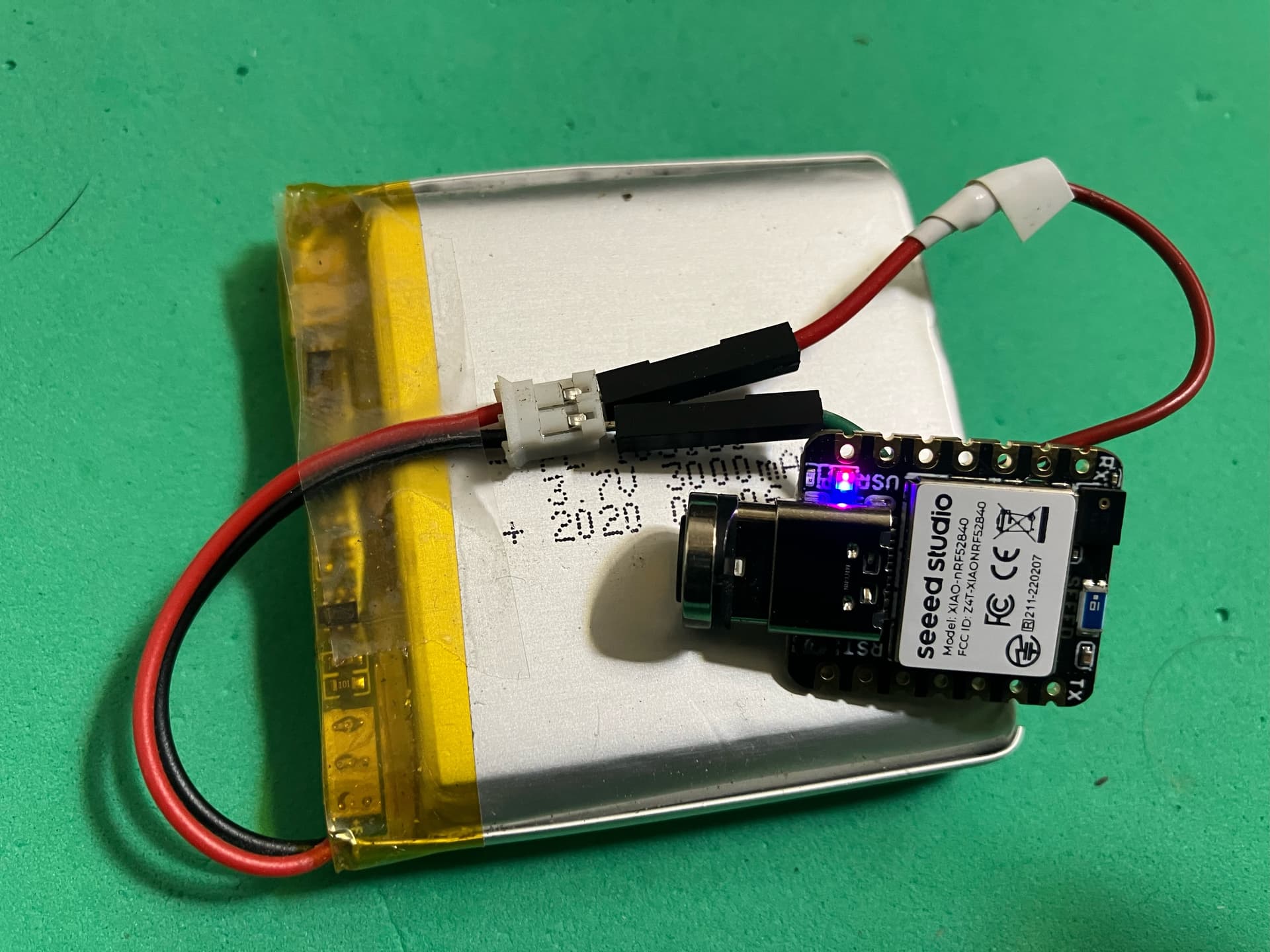
Ok, so I’m using a XIAO 52840 Sense with a battery connected to the VBAT pad on the bottom, and everything is almost working as expected. Almost.
When I disconnect the device from USB, one main problematic thing happens:
- I lose radio connectivity. I have to power down the radio, power back up and re-apply configuration
I am using the nrf_to_nrf library for the radio but I suspect simlar behaviour with bluetooth.
I am wondering two main things:
a. Can I prevent the radio from dying out when USB is disconnected?
b. If not a, how can I detect this change in real-time, so I can immediately power down the radio and get it working again?
I tried some basic things like verifying some radio settings are correct, trying to watch for NRF_POWER->EVENTS_USBREMOVED but that isn’t working either…
i wonder if it is a power brownout issue, or some lag in switching over from usb to battery power
If its a brownout issue, you will not be able to detect fast eniugh, so try boosting the batyery voltage, current supply, maybe connect a power supply inplace of the battery and see if that changes anything
if it is a final instalation cant you just boot from battery power
To answer your question, some say you can detect usb by sensing if power is on the 5v pin, as this pin is powered by the usb, you would have to divide the voltage and bring over to a 3.3v pin for detection, but like i said i dont think you could switch fas enough to make a difference
Technically it doesnt detect if usb Communications is present… only if usb POWER is present
Thanks for the info.
I’m now testing out using RF_POWER->USBREGSTATUS along with a timer to trigger a radio reset only once after USB power is disconnected and its working!
The funny thing is that the datasheet says “VBUS input detection status (USBDETECTED and
USBREMOVED events are derived from this information)” but I don’t seem to get the USBREMOVED event.
I will try later with a bench power supply as per your suggestion instead of a battery and see if I still encounter the same behaviour.
cool i am not familure with the XIAO Nrf52 yet, i just got my, I use the XIAO ESP32 more offen
Hi there,
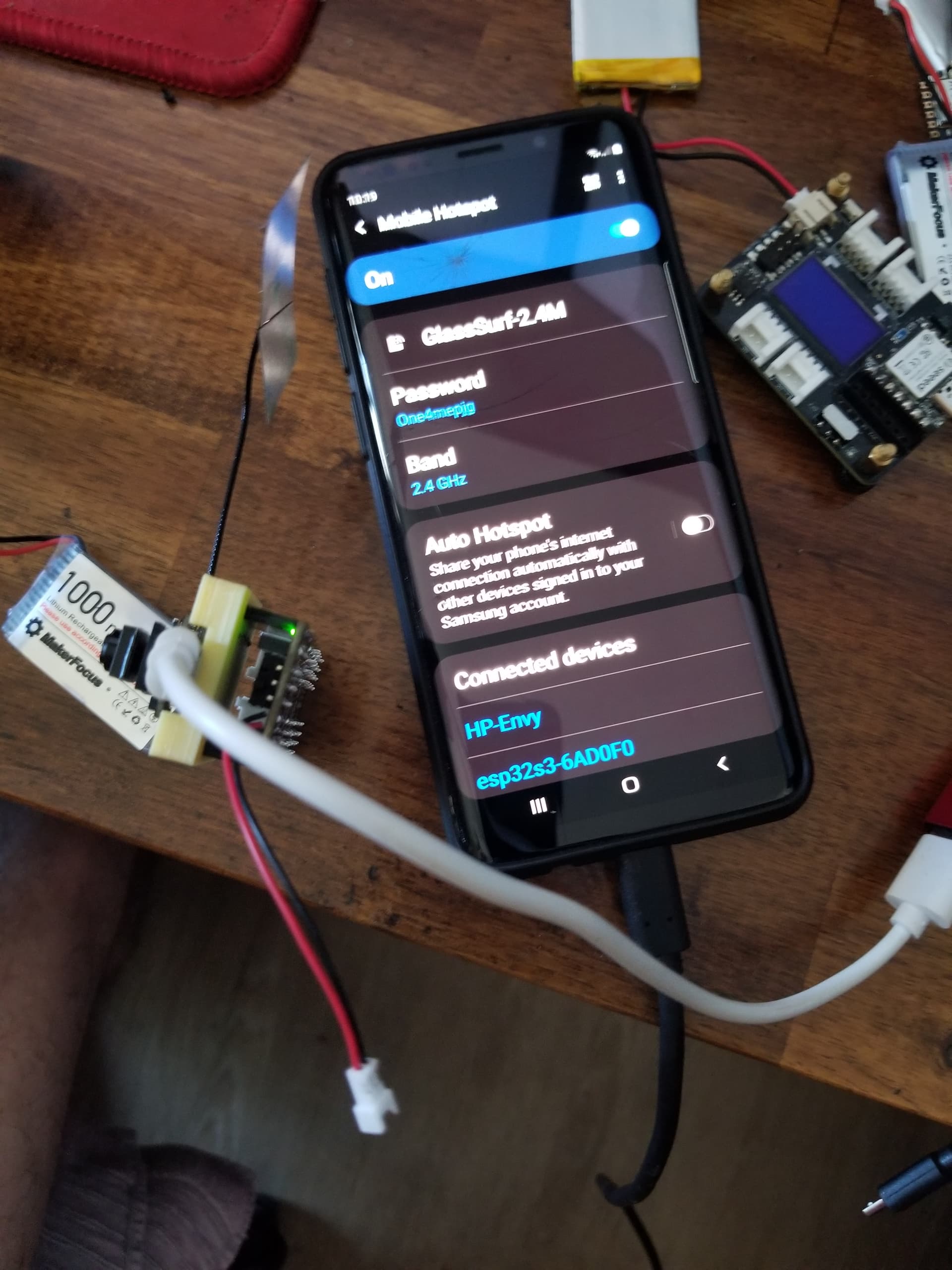
I’m able to use the Arduino_BLE Library and connections to Mobile phone (sammy S9+) or Desktop (Nrf_connect) without issue when connecting the USB and Disconnecting While the BLE connection is Stable. Must be a good battery btw, with internal protection or BMS.
i.e. I can Run on Battery, a BLE Central on the Expansion Board, with added Xiao Battery directly connected and disconnect the USB without A reset or dropping the connection.
I suspect it’s a LIB issue for you.
HTH
GL  PJ
PJ

Hmm, very interesting, I will have to investigate further on what exactly is happening that only affects the radio.
I tried using a bench power supply and got the exact same behaviour. Something goes wrong with the radio, and the only way I know how to bring it back is to completely power it down, back up and reconfigure.
… I assume according to his response he has properly troubleshot the brownout issue…
… ps I just realized from that other guy that new users are not allowed to post pictures until they get some trust under their belt… fyi
Hmm, nothing added really just the simplest of setups for testing:
I’ve reverted to testing with just the gettingStarted example from the nrf_to_nrf library to simplify use of the radio.
/*
 * See documentation at https://nRF24.github.io/RF24
 * See License information at root directory of this library
 * Author: Brendan Doherty (2bndy5)
 */

/**
 * A simple example of sending data from 1 nRF24L01 transceiver to another.
 *
 * This example was written to be used on 2 devices acting as "nodes".
 * Use the Serial Monitor to change each node's behavior.
 */
#include "nrf_to_nrf.h"

// instantiate an object for the nRF24L01 transceiver
nrf_to_nrf radio;  // using pin 7 for the CE pin, and pin 8 for the CSN pin

// Let these addresses be used for the pair
uint8_t address[][6] = { "1Node", "2Node" };
// It is very helpful to think of an address as a path instead of as
// an identifying device destination

// to use different addresses on a pair of radios, we need a variable to
// uniquely identify which address this radio will use to transmit
bool radioNumber = 1;  // 0 uses address[0] to transmit, 1 uses address[1] to transmit

// Used to control whether this node is sending or receiving
bool role = false;  // true = TX role, false = RX role

// For this example, we'll be using a payload containing
// a single float number that will be incremented
// on every successful transmission
float payload = 0.0;

void setup() {

  Serial.begin(115200);
  while (!Serial) {
    // some boards need to wait to ensure access to serial over USB
  }

  // initialize the transceiver on the SPI bus
  if (!radio.begin()) {
    Serial.println(F("radio hardware is not responding!!"));
    while (1) {}  // hold in infinite loop
  }

  // print example's introductory prompt
  Serial.println(F("RF24/examples/GettingStarted"));

  // To set the radioNumber via the Serial monitor on startup
  Serial.println(F("Which radio is this? Enter '0' or '1'. Defaults to '0'"));
  while (!Serial.available()) {
    // wait for user input
  }
  char input = Serial.parseInt();
  radioNumber = input == 1;
  Serial.print(F("radioNumber = "));
  Serial.println((int)radioNumber);

  // role variable is hardcoded to RX behavior, inform the user of this
  Serial.println(F("*** PRESS 'T' to begin transmitting to the other node"));

  // Set the PA Level low to try preventing power supply related problems
  // because these examples are likely run with nodes in close proximity to
  // each other.
  radio.setPALevel(NRF_PA_LOW);  // RF24_PA_MAX is default.

  // save on transmission time by setting the radio to only transmit the
  // number of bytes we need to transmit a float
  radio.setPayloadSize(sizeof(payload));  // float datatype occupies 4 bytes

  // set the TX address of the RX node into the TX pipe
  radio.openWritingPipe(address[radioNumber]);  // always uses pipe 0

  // set the RX address of the TX node into a RX pipe
  radio.openReadingPipe(1, address[!radioNumber]);  // using pipe 1

  // additional setup specific to the node's role
  if (role) {
    radio.stopListening();  // put radio in TX mode
  } else {
    radio.startListening();  // put radio in RX mode
  }

  // For debugging info
  // printf_begin();             // needed only once for printing details
  // radio.printDetails();       // (smaller) function that prints raw register values
  // radio.printPrettyDetails(); // (larger) function that prints human readable data

}  // setup

void loop() {

  if (role) {
    // This device is a TX node

    unsigned long start_timer = micros();                // start the timer
    bool report = radio.write(&payload, sizeof(float));  // transmit & save the report
    unsigned long end_timer = micros();                  // end the timer

    if (report) {
      Serial.print(F("Transmission successful! "));  // payload was delivered
      Serial.print(F("Time to transmit = "));
      Serial.print(end_timer - start_timer);  // print the timer result
      Serial.print(F(" us. Sent: "));
      Serial.println(payload);  // print payload sent
      payload += 0.01;          // increment float payload
    } else {
      Serial.println(F("Transmission failed or timed out"));  // payload was not delivered
    }

    // to make this example readable in the serial monitor
    delay(1000);  // slow transmissions down by 1 second

  } else {
    // This device is a RX node

    uint8_t pipe;
    if (radio.available(&pipe)) {              // is there a payload? get the pipe number that recieved it
      uint8_t bytes = radio.getPayloadSize();  // get the size of the payload
      radio.read(&payload, bytes);             // fetch payload from FIFO
      Serial.print(F("Received "));
      Serial.print(bytes);  // print the size of the payload
      Serial.print(F(" bytes on pipe "));
      Serial.print(pipe);  // print the pipe number
      Serial.print(F(": "));
      Serial.println(payload);  // print the payload's value
    }
  }  // role

  if (Serial.available()) {
    // change the role via the serial monitor

    char c = toupper(Serial.read());
    if (c == 'T' && !role) {
      // Become the TX node

      role = true;
      Serial.println(F("*** CHANGING TO TRANSMIT ROLE -- PRESS 'R' TO SWITCH BACK"));
      radio.stopListening();

    } else if (c == 'R' && role) {
      // Become the RX node

      role = false;
      Serial.println(F("*** CHANGING TO RECEIVE ROLE -- PRESS 'T' TO SWITCH BACK"));
      radio.startListening();
    }
  }

}  // loop
When I add the following code, the radio will work after switching from USB to battery.
bool test =0;

void loop() {

 if( !(bitRead(NRF_POWER->USBREGSTATUS,0)) && test == 0){
        test = true;
        radio.powerDown();
        radio.powerUp();
        radio.setChannel(50);
 }else
 if(bitRead(NRF_POWER->USBREGSTATUS,0)){
       test = false;
 }
Where I have it modified to work on channel 50, forgot to add that to the code.
Hi there,
Battery looks good… 
I’m sure you finger it to unplug it… That’s NOT gonna fly ever.
HTH
GL  PJ
PJ
get a Proper platform to test on. AIR mode is not supported… LOL
I use the Magnetic connection as well , does work good for quick connection but NOT hanging a big magnet on the USB c directly it is going to have it’s effect.(IMU) I use a 6’ pigtail for best results.
I bet if you place a big cap on the power and Gnd it will be less affected by unplugging it.
There is some code to detect the USB is connected in another thread on here, may be worth a LQQK
… yeah that was news to me… I have not dove into the Nrf stuff yet
… this would trouble shoot so
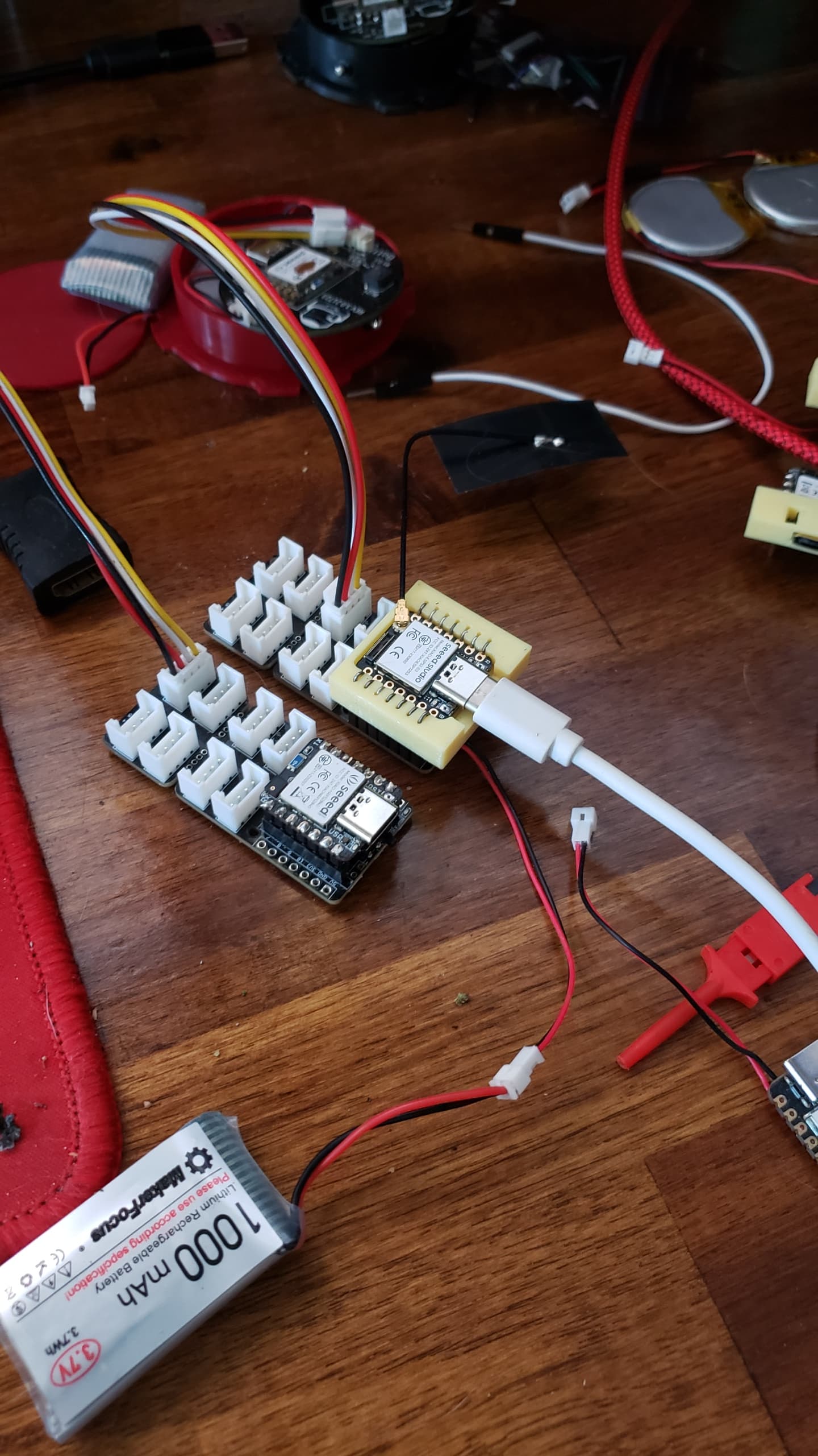
Much better if you had xiao grove expansion board
I do! Same behaviour if I have the battery switch set to ON and I disconnect from USB. I thought it would be more straight forward if I posted a pic of just the XIAO connected to battery and test with that.
What is that? A wireless usb dongle?
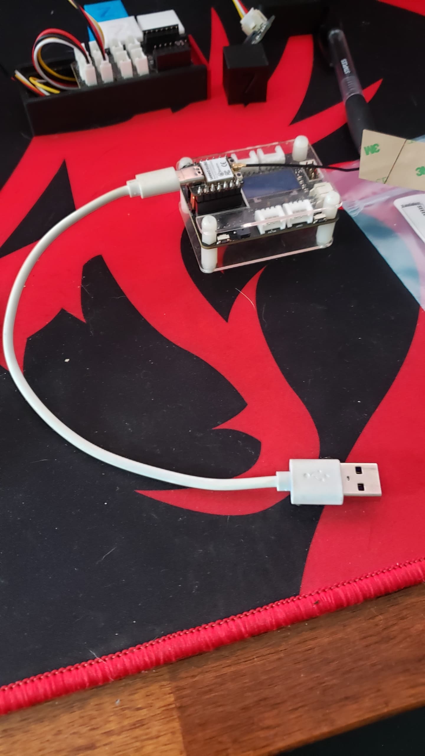
No hehe, its just a magnetic USB cable.
Hi TMRh20Projects,
Since no one else has asked the question, I would like to confirm.
Have you measured the battery voltage when the USB is not connected? How many volts?
I have a few batteries at nearly full charge, but the main one I’m testing with reads 3.85v right now. Measured with a multimeter & via the XIAO VBAT pin. I might try a large capacitor connected to the 5v rail, but other than that I’m out of ideas.