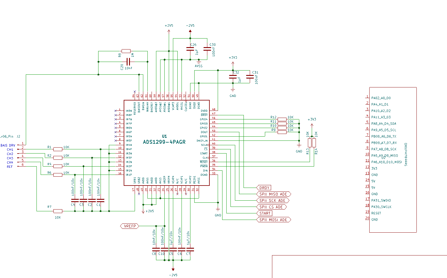
I have been trying to connect the nrf52840 sense board with ads1299-4. I have designed a schematic but I am not sure which pin should I connect from ads1299 to sense board. I have found the kiCad symbol from the website itself so I assume it is going to be a proper symbol for sense board.
Hi there,
Are you planning to use it as a SPI device, pretty straight forward the data sheet speaks to it here:
4 spi signals and a DRDY active low coming back as an interrupt for data ready…(any GPIO input)
Have you bread boarded it?
What is your application for this? I see it has good “lead off & On” detection for medical devices?
HTH
GL ![]()
5.2 SPI Interface

The SPI-compatible serial interface consists of four signals: CS, SCLK, DIN, and DOUT. The interface reads
conversion data, reads and writes registers, and controls ADS1299-x operation. The data-ready output, DRDY
(see the Data Ready (DRDY) section), is used as a status signal to indicate when data are ready. DRDY goes
low when new data are availab
The ADS1299 typically uses the SPI (Serial Peripheral Interface) protocol for communication. The Seeed XIAO nRF52840 Sense board should have built-in SPI functionality. Connect the appropriate SPI pins (such as fairfaxautodetailng, MISO, MOSI) between the two devices.
Hey PJ_Glasso,
Thank you for the reply ![]() Yes, I would like to connect it using SPI. You are absolutely right that the there are four SPI signals and 1 DRDY but I am still confused which SPI pin goes where.
Yes, I would like to connect it using SPI. You are absolutely right that the there are four SPI signals and 1 DRDY but I am still confused which SPI pin goes where.
I am going to use it for measuring EEG signals using dry EEG electrodes.
Also, can I use common power supply for the module?
Hi ,
Yea I would use the DRDY pin as an Interrupt pin on the Xiao D1 INPUT
The Chip select D6 from Xiao OUTPUT as well as the Start signal also would be an Output from the Xiao D7. The clock and Master Out and Master Output Slave Input, Master Input Slave Output standard.
something along theses lines. LOL in paint …
HTH
GL:-)
PJ
You might have done it paint but this picture helps me a ton. Thanks a lot man.
NO problem, Are you going to sample synchronized, PIN 37 CLK in is used or tied High to 10K resistor. FYI
HTH
GL ![]() PJ
PJ
Thank you once again for that extra bit of information. I need to review my other ADS schematic with someone who have worked on a similar project before. Thank you so much again. ![]()
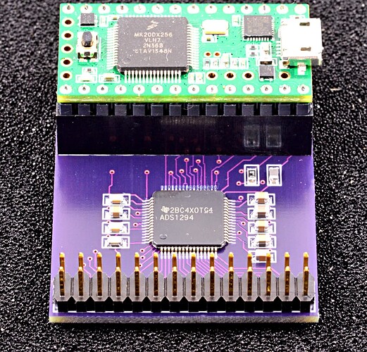
No Problem, here is a link to a project with board and code. Definitely worth the read.
GL ![]() PJ
PJ
I have seen this already… but I am really new to schematic design, hence dumb questions from my side … ![]()
Did you manage to launch the project?
Think of the bandwidth for this!


