Hi all
I’m not having much luck with my Xiaos, neither of the two sketches I want to use will work.
The first requires EEPROM, so wont compile as there is no EEPROM on the Xiao, so any sketch that uses that will fail.
The second simpler sketch compiles & uploads but doesn’t seem to be doing anything
Apart from very basic routines e.g. flash or fade, virtually everything else i’ve tried either compiles & uploads but doesn’t run or just throws up loads of errors during compilation.
Both the Xiaos I have do work as I can input and output from them
I have tried on both the Arduino IDE 1.18.19 & IDE 2 rc5
Cheers
Keith
The Adafruit QT Py is very similar to the Xiao and is available with EEPROM. I’ve used Xiao on several projects some of which where xfered from Arduino boards and had very little trouble. what do you mean by : compiles & uploads but doesn’t seem to be doing anything ?? What is it supposed to be doing that it is not ? No messages ? No LED’s ?
Lots of errors on something that compiles normally is often related to wrong libraries. Xiao uses a different CPU (much faster) than Nano and so uses many different libraries than Arduino. Turn on ‘verbose’ under ‘preferences’ to call out those errors. Maybe show us what some of the problems you are having.
One very important detail is that Xiao’s are 3.3V and Nanos & many Arduino bd are 5V.
Library incompatibilty seems to be the problem, the sketches I have tried that fail to comply are trying to call libraries that do not exist/are not available for the Xiao. Hence my Topic title.
This one compiles and uploads with no errors but does not work (It works as is on a Nano):
```cpp
#include <DCC_Decoder.h>


#define NUMACCESSORIES 2 // Enter the number of accessories here

// GO TO setup() TO CONFIGURE DCC ADDRESSES AND PIN NUMBERS


  typedef struct DCCAccessoryData {
  int   address;   // User Configurable DCC address
  byte  outputpin1; // User Configurable Arduino pin
  byte  outputpin2; // User Configurable Arduino pin
  byte  dccstate;  // Internal use DCC state of accessory, 1=on, 0=off
};
DCCAccessoryData accessory[NUMACCESSORIES];

// The DCC library calls this function to set / reset accessories
void BasicAccDecoderPacket_Handler(int address, boolean activate, byte data) {
  address -= 1;
  address *= 4;
  address += 1;
  address += (data & 0x06) >> 1;
  // address = address - 4; // uncomment this line for Roco Maus or z21
  boolean enable = (data & 0x01) ? 1 : 0;
  for (byte i=0; i<NUMACCESSORIES; i++) {
    if (address == accessory[i].address) {
      if (enable) accessory[i].dccstate = 1;
      else accessory[i].dccstate = 0;
    }
  }
}

void setup() {
// CONFIGURATION OF ACCESSORIES
// Copy & Paste as many times as you have accessories
// The amount must be same as NUMACCESSORIES
// Don't forget to increment the array index
  accessory[0].address   = 505; // DCC address
  accessory[0].outputpin1 = 3; // Arduino pin
  accessory[0].outputpin2 = 4; // Arduino pin

  accessory[1].address   = 506; // DCC address
  accessory[1].outputpin1 = 5; // Arduino pin
  accessory[1].outputpin2 = 6; // Arduino pin
  /*
  accessory[2].address   = 507; // DCC address
  accessory[2].outputpin1 = 9; // Arduino pin
  accessory[2].outputpin2 = 10; // Arduino pin

  accessory[3].address   = 508; // DCC address
  accessory[3].outputpin1 = 11; // Arduino pin
  accessory[3].outputpin2 = 12; // Arduino pin
  */


// END OF CONFIGURATION OF ACCESSORIES

  DCC.SetBasicAccessoryDecoderPacketHandler(BasicAccDecoderPacket_Handler, true);
  DCC.SetupDecoder( 0x00, 0x00, 0 );

  for(byte i=0; i<NUMACCESSORIES; i++) {
    pinMode     (accessory[i].outputpin1, OUTPUT);
    digitalWrite(accessory[i].outputpin1, LOW);
    pinMode     (accessory[i].outputpin2, OUTPUT);
    digitalWrite(accessory[i].outputpin2, HIGH);
  }
}

void loop() {
  DCC.loop(); // Call to library function that reads the DCC data

  for(byte i=0; i<NUMACCESSORIES; i++) {
    if (accessory[i].dccstate)
      (digitalWrite(accessory[i].outputpin2, LOW), digitalWrite(accessory[i].outputpin1, HIGH));

    else
      (digitalWrite(accessory[i].outputpin1, LOW), digitalWrite(accessory[i].outputpin2, HIGH));
  }
}
 Pins 3,4,5 & 6 should switch on a data received on pin 2 (This is the default pin)
They do nothing

Keith
Following the if & else statement on loop(), each has two statements surrounded by parenthesis & not braces.
EDIT : well, I’ve never seen that syntax before but it compiles.
Xiao runs many times faster than a Nano, are you looking at the output signals with a scope or a meter ?
I have used the pins as outputs & they do seem to work as expected. Have you tried just setting then statically ?
IE
pinMode (3, OUTPUT);
digitalWrite(3, LOW);
pinMode (4, OUTPUT);
digitalWrite(4, HIGH);
while(1)
;
* List item
Interesting that you have picked up on parenthesis & braces as it works on an Arduino and all I did was comment out the two addresses not being used. 
It’s exactly the same structure as the original example sketch I started with from DCC_Decoder_Master library
I have tried setting the pins statically, I set up a button test using pin 2 as input and looked for change of state on 3,4,5 & 6.
The program is for DCC model railway control of LED signals.
The input signal to pin 2 is a 8kHz ‘square’ wave, max level 3.3v, encoded with data. I can read & decode this with my scope, so that is correct.
When a command is sent (on the address selected, in this case 505 or 506 etc.) the pins will change state and stay at that state until a command to the contrary is sent. So the outputs are eitrher HIGH or LOW and used to drive LEDS at approx 3mA
(When the Xiao is first powered up the pairs of outputs go to the states, low, high & low, high.)
I’ve already built several units based on this library and sketch without a problem but I wanted something smaller so picked the Xiao.
Not clear to me if you where successful with the static test setting outputs to a known state.
If the outputs STILL don’t work go back to the most basic test, unconnected to anything, set to a state i.e. digitalWrite(3, high) assure that works then digitalWrite(3, low) assure that works . Don’t confuse the issue with anything else until it will pass the simplest of tests.
Interesting you mentioned the drive needed at 3ma. I have a pending question with the forum that has not been answered. I’ll repost it :
According to the SAMD21 datasheet
Driver Strength = 0 [“Normal” Drive strength]:
I Out Low @ 3.00-3.63V: 2.4mA
I Out High @ 3.00-3.63V: 2.0mA
Driver Strength = 1 [“Stronger” Drive strength --]:
I Out Low @ 3.00-3.63V: 10mA
I Out High @ 3.00-3.63V: 7mA
How is the device configured ? If Normal & not Stronger how can it be set to Stronger
using C commands ?
As regards driver strength; I found plenty of discussion online and it seems it’s a bit of a mystery for many users. There are some software fixes to turn it to high from the default low.
However attempting to draw more current when in default low mode doesn’t seem to destroy the chip, it just pulls the output down. One user was pulling enough current to drop the voltage from 3.3v down to 2.5v without a problem.
In my case I am driving LTV844 opto couplers with a 470R series resistor from the output pin.
It drops the output to around 2.8v and is sourcing about 3.6mA. It hasn’t done any damage so far even
being on for long periods. Any less is too little drive current for the opto.
Still doesn’t solve why the DCC decoder doesn’t work on a Xiao 
As regards the pin test; I set up pin 2 as INPUT and used a push button to VCC via a R.
I set the 4 output pins to OUTPUT
I then read the state of the push button and passed it to each of the output pins in turn
When I pressed the button the relevant output changed LOW to HIGH. So I assume the pins work as expected.
I have since run this short sketch to prove the pins again, this time with the LED load on each output pin
```cpp


void setup() {
  pinMode(3, OUTPUT);
  pinMode(4, OUTPUT);
  pinMode(5, OUTPUT);
  pinMode(6, OUTPUT);
     }

void loop() {
  for (int i = 3; i <= 6; i++) {
    digitalWrite(i, HIGH);
    delay(500);
    digitalWrite(i, LOW);
    delay(100);
   }
}
So your output pins are working for you, great. I’d surely expect the output voltage to drop as the available current is being exceeded. I’d also expect a higher failure rate long term.
I’d be interested in the software fixes to turn output strength to high from the default low, will you post them or point me to them ?
Post more info about the failing DCC decoder.
FWIW a current project, that I wanted to use a XIAO on, has been changed to a Pro Mini mostly due to drive issues. Not much bigger then a Xiao, 5V & same CPU family as Nano. It’s a decent choice if no serial is needed and one has or doesn’t mind buying the programming module. https://www.amazon.com/DSD-TECH-SH-U09C5-Converter-Support/dp/B07WX2DSVB
I went to gitHub and looked at DCC_Decoder.cpp/h. I didn’t dig very deep but an unknown are the areas that deal with interrupts. Nothing specific jumps out but an area to think about if you haven’t already.
Bit of a struggle for me getting some understanding of the library code. Is it true that your controlling data stream is coming in on pin 2 via interrupt ? If so have you verified that the interrupt is being recognized ?
Thanks for looking deeper into the operations.
How would I verify an interrupt is recognized? That is something I haven’t had to deal with before.
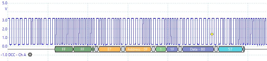
This is a sample of a data stream on pin 2:
Note that might not be triggered at the start of a packet.
This is description of a packet: https://dccwiki.com/Digital_Packet
The data is determined by the period of the square wave 58uS = 1, 100uS = 0
Cheers
Let me see if I understand a little of what’s going on. Data stream comes in on pin 2 that provides information that controls your 4 output pins. Independently you can control the output pins. You have data on pin 2 but not control of the output pins from the data stream. Is my understanding correct ?
That’s correct.
What I have is an accessory (or stationary) DCC decoder. They are meant for controlling devices that have two states e.g. on/off, open/closed, red/green etc.
From the DCC command station I am sending, at an address of 505 (or 506), the commands “on” or “off”
If the address set in the decoder is either of those addresses, output pins 3 & 4 (or 5 & 6) should change state as I send those commands.
That is not happening.
OK then I’m thinking either the interrupt isn’t being recognized or the data interpretation is going astray.
Make a backup copy of DCC_decoder.cpp & .h
Somewhere in your program you define the interrupt pin: #define kDCC_INTERRUPT 2 // make sure it says 2 for your interrupt pin
To see if the interrupt is being recognized by putting an indicator :
find the ISR DCC_Decoder::DCC_Interrupt() about line 50 in DCC_decoder.cpp
insert the line Serial.print(func); // this will print ISR name DCC_Interrupt on the serial monitor when the interrupt happens UNLESS Serial.print() is inhibited by the interrupt.
Run the program, send the data stream to pin 2 and see if the message is printed, if not then use indicator plan B
Plan B
Set an output pin to a known state (ie High) in Setup() Set it to the opposite state (ie low) in DCC_Interrupt(). Assure each state happens when it should.
If not seeing opposite state at interrupt then the interrupt isn’t getting thru.
Back to the subject of output drive strength : This from another forum. It compiles OK but I haven’t tested it.
To increase a given pin’s driver strength and allow it to source 7mA and sink 10mA, just add the following line after calling the pinMode() function. In this example the driver strength of digital pin D7 is increased:
PORT->Group[g_APinDescription[7].ulPort].PINCFG[g_APinDescription[7].ulPin].bit.DRVSTR = 1;
Subsequent calls to the digitalWrite() function don’t affect the DRVSTR bit in any way.
Previously you tested the outputs unconnected to the load with success. Are the outputs also able to drive the load when tested that way ?
There wasn’t that line anywhere in the program - I have added it, it doesn’t make any noticeable difference.
I think I spotted that whilst hunting for answers.
I tested the outputs connected to the leds.
OK Interrupt set by another name. How about a call to SetupDecoder() with 3 parameters. The 3rd parameter is interupt pin ? Or a call to StartInterrupt(interrupt); ?
Data stream in pin A2/D2 ?
I tried hunting back through the libraries to see where the interrupt is defined.
It’s a bit over my head but I found that the library “arduino.h” is an #include, that itself has #include “Interrupt.h”
However, the Arduino “interrupt.h” includes code, the Seeed interrupt is just a dummy file with comments!
Looks like the interrupt needs to be defined differently when using the Xiao compared to an Arduino.
The pin the interrupt on is ultimately declared via StartInterrupt(interrupt). Library DCC_Decoder called that in routine SetupDecoder() & uses the 3rd parameter. Find those & trace them back to your program.
Is Data stream in pin A2/D2 ?
Did you try the trap in the ISR routine called out a couple of messages back ?
Hi again.
Been finishing another project before coming back to this.
I also needed to do a small re-wire on the board so I could use the Xiao USB whilst the DCC signal was applied
I didn’t trap the ISR routine, as to be honest, I got a bit lost in what needs to be done.