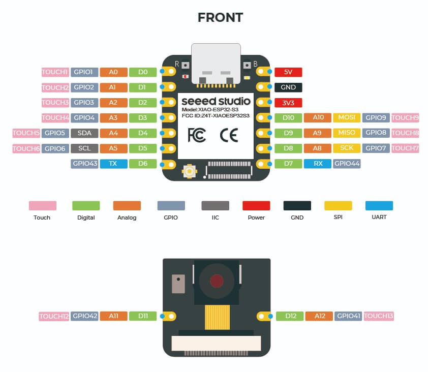
Please show me the connection between the SSD and S3, the pin names of S3 should follow the “XIAO ESP32S3/XIAO ESP32S3 Sense Pin List” in the Wiki.
Show me the link of SSD1309.
Please post a sketch.
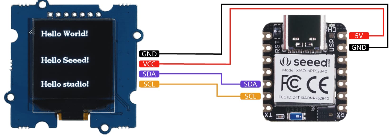
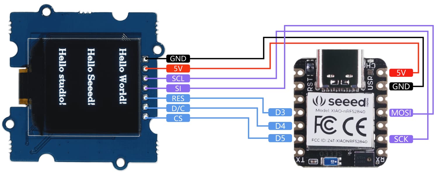
On the back of the display there are 2 solder jumper points. IIC and SPI. It’s soldered on the SPI. I’m still learning so I don’t know the relation between SPI and i2C protocols, but this board is set for SPI and definitely not IIC.
Easy button (for now), I will flip the pins 4 and 5. Give me a sec.
It’s a common thing with these, kinda Hybrid IMO, I often think its set right but wired wrong, or wired correct but programmed(#defines) wrong, or the pins I use for one MCU are different for another.
So there is a few permutations then add which interface SPI or I2C and you can see where I’m going…can get real fuzzy quick.
follow what @msfujino asks you’ll be going in no time and we all learn something!
Yes, I’m figuring that out as I am learning. Things are all mixed up and it’s amazing that we can get anything to work. I’m just glad there are smarter people than me out there that are willing to help.
It’s NOT rocket SCience , but there is a process to the setup and some nuance between Xiao’s. The PINS and using the GPIO pin numbers versus the LOGICAL pin Names, D1,D2,D3 etc… or 2, 4, 7,8 ;
ALso the Preconfigured more or less Peripheral port pins.
for SPI, and I2C and I2S You see them listed in there respective colors for each, but also NOTE the GPIO numbers are different.
Always start there, is what @msfujino is alluding to if it’s SPI.
as he said if you can post a picture of the back where the jumper is
You’ll get it. Just takes a few Swings at the ball…