Hi,
I have recently bought a Grove IMU 9DOF v2 (no Seeeduino or Base shield is available!)
I intend the imu directly to Arduino Uno, I wonder how the connection should be and how the provided example (IMU_9DOF_Demo_Compass_Calibrated) should be updated accordingly?
Thanks!
Hi @navid_km
| Arduino uno | Grove-IMU_9DOF_v2.0 |
|---|---|
| 5V | VCC |
| GND | GND |
| SDA | SDA(27) |
| SCL | SCL(28) |
| The Arduino UNO pinout diagram in the below.! | |
| [arduino-uno-pinout-diagram | 690x493](upload://6DYAdOolt16Pm6Sf4ddM1mbXGKu.jpeg) |
Thanks for the reply.
I have connected imu SDA to pin 27 (A4) and SCL to pin 28 (A5) of the Arduino. But when running the example code IMU_9DOF_Demo_Compass_Calibrated, I get the “MPU6050 connection failed” error.
I wonder how the code should be modified?
Shall I add the following as mentioned in the documentations? If so which PinMode should I use?
pinMode(xx, OUTPUT);
digitalWrite(xx,1);
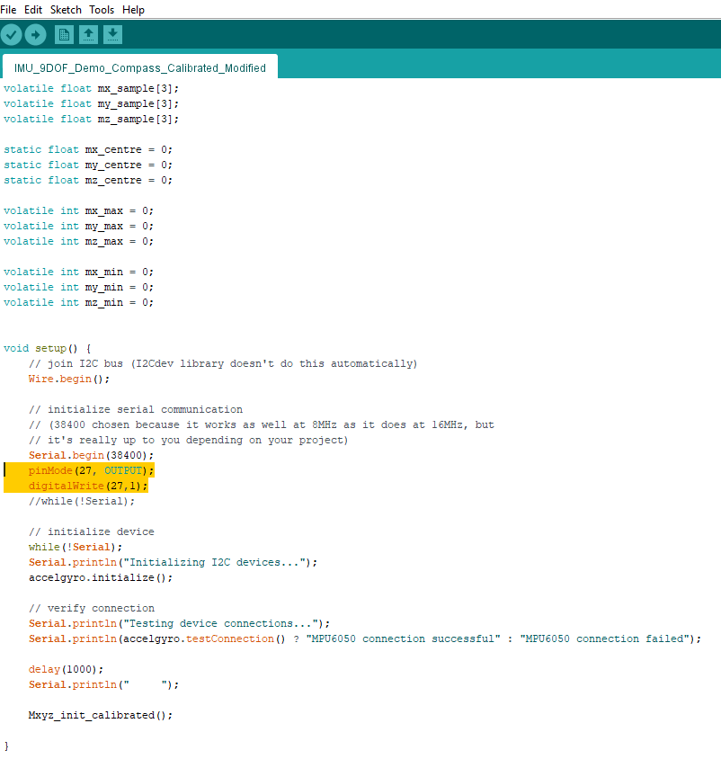
I tested with and without the mentioned 3 lines of code, but I still get the “MPU6050 connection failed” error.
Hi @navid_km
If the monitor display “MPU6050 connection failed which means there should be some places where the wiring is not connected properly.
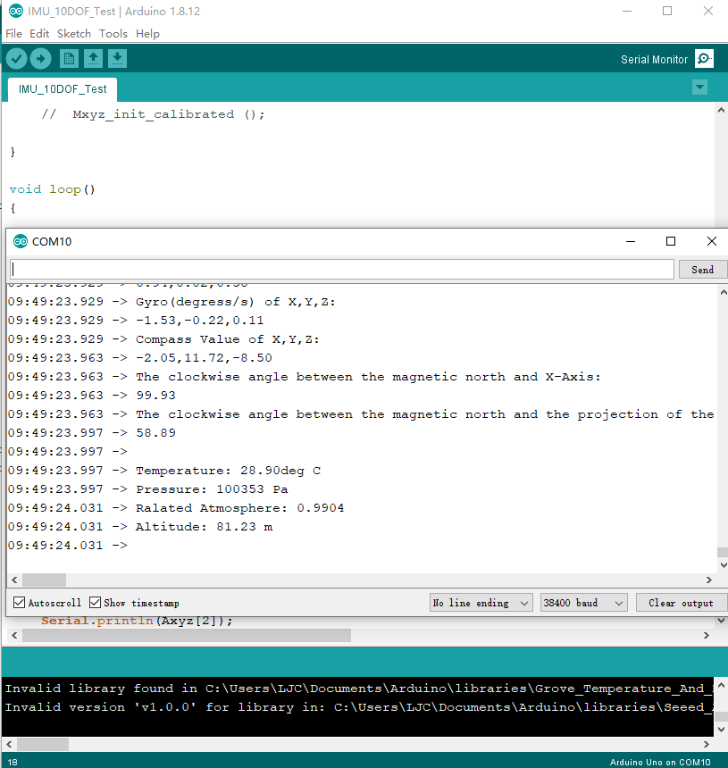
Because there is no 9DOF in my hand, so I use 10DOF to do the same test.

@navid_km double check the jumper wires, use a multimeter and check the continuity.
Hi @salman, thanks for the reply, by default they are connected to support I2C, but I will double check.
@jiachenglu, yes this is exactly how I connected! I also tested with SCL/SDA on the other side of the Arduino A4/A5 as you mentioned earlier, but still the same error…
I didn’t get if I should add the following code or not?
pinMode(xx, OUTPUT);
digitalWrite(xx,1);

Hi @navid_km
Arduino UNO doesn’t need to add the code you listed.
Because the lorawan board needs to pull up the pin level
of a peripheral to open I2C communication
Thanks for the reply. Then I assume that the sensor is broken…
Hi @navid_km
Do you have any other Arduino board to do the same test?
It seems that the Arduino board in your hand is different from the official version.
Unfortunately not, is there any other way to test the I2C in Arduino?
@navid_km You can use this I2C scanner to scan the I2C device in Arduino: https://gist.github.com/tfeldmann/5411375
Hi @salman, thanks indeed for the support.
I tested the code, if I conenct the imu it finds it. And if I disconnect it, there is no I2C device found:
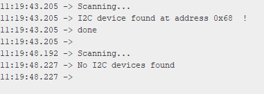
So it seems that the I2C of the Arduino is working properly.
@navid_km thin conclude the grove module I2C and Arduino I2C is working fine, you can use the address with an example sketch and try.
I tried specifically with this address, although the default is also 0x68, but still the same error. I also tried with totally different codes from the internet, and the same results…
Here is the code from the tutorial:
#include "Wire.h"

// I2Cdev and MPU6050 must be installed as libraries, or else the .cpp/.h files
// for both classes must be in the include path of your project
#include "I2Cdev.h"
#include "MPU6050.h"

// class default I2C address is 0x68
// specific I2C addresses may be passed as a parameter here
// AD0 low = 0x68 (default for InvenSense evaluation board)
// AD0 high = 0x69
MPU6050 accelgyro(0x68);
I2Cdev   I2C_M;

uint8_t buffer_m[6];

int16_t ax, ay, az;
int16_t gx, gy, gz;
int16_t   mx, my, mz;

float heading;
float tiltheading;

float Axyz[3];
float Gxyz[3];
float Mxyz[3];
#define sample_num_mdate  5000

volatile float mx_sample[3];
volatile float my_sample[3];
volatile float mz_sample[3];

static float mx_centre = 0;
static float my_centre = 0;
static float mz_centre = 0;

volatile int mx_max = 0;
volatile int my_max = 0;
volatile int mz_max = 0;

volatile int mx_min = 0;
volatile int my_min = 0;
volatile int mz_min = 0;

void setup() {
    // join I2C bus (I2Cdev library doesn't do this automatically)
    Wire.begin();

    // initialize serial communication
    // (38400 chosen because it works as well at 8MHz as it does at 16MHz, but
    // it's really up to you depending on your project)
    Serial.begin(38400);

    // initialize device
    while(!Serial);
    Serial.println("Initializing I2C devices...");
    accelgyro.initialize();

    // verify connection
    Serial.println("Testing device connections...");
    Serial.println(accelgyro.testConnection() ? "MPU6050 connection successful" : "MPU6050 connection failed");

    delay(1000);
    Serial.println("     ");

    Mxyz_init_calibrated();
}

void loop() {

    getAccel_Data();
    getGyro_Data();
    getCompassDate_calibrated(); // compass data has been calibrated here
    getHeading();				//before we use this function we should run 'getCompassDate_calibrated()' frist, so that we can get calibrated data ,then we can get correct angle .
    getTiltHeading();

    Serial.println("calibration parameter: ");
    Serial.print(mx_centre);
    Serial.print("         ");
    Serial.print(my_centre);
    Serial.print("         ");
    Serial.println(mz_centre);
    Serial.println("     ");
    Serial.println("Acceleration(g) of X,Y,Z:");
    Serial.print(Axyz[0]);
    Serial.print(",");
    Serial.print(Axyz[1]);
    Serial.print(",");
    Serial.println(Axyz[2]);
    Serial.println("Gyro(degress/s) of X,Y,Z:");
    Serial.print(Gxyz[0]);
    Serial.print(",");
    Serial.print(Gxyz[1]);
    Serial.print(",");
    Serial.println(Gxyz[2]);
    Serial.println("Compass Value of X,Y,Z:");
    Serial.print(Mxyz[0]);
    Serial.print(",");
    Serial.print(Mxyz[1]);
    Serial.print(",");
    Serial.println(Mxyz[2]);
    Serial.println("The clockwise angle between the magnetic north and X-Axis:");
    Serial.print(heading);
    Serial.println(" ");
    Serial.println("The clockwise angle between the magnetic north and the projection of the positive X-Axis in the horizontal plane:");
    Serial.println(tiltheading);
    Serial.println("   ");
    Serial.println("   ");
    Serial.println("   ");
    delay(300);
}

void getHeading(void) {
    heading = 180 * atan2(Mxyz[1], Mxyz[0]) / PI;
    if (heading < 0) {
        heading += 360;
    }
}

void getTiltHeading(void) {
    float pitch = asin(-Axyz[0]);
    float roll = asin(Axyz[1] / cos(pitch));

    float xh = Mxyz[0] * cos(pitch) + Mxyz[2] * sin(pitch);
    float yh = Mxyz[0] * sin(roll) * sin(pitch) + Mxyz[1] * cos(roll) - Mxyz[2] * sin(roll) * cos(pitch);
    float zh = -Mxyz[0] * cos(roll) * sin(pitch) + Mxyz[1] * sin(roll) + Mxyz[2] * cos(roll) * cos(pitch);
    tiltheading = 180 * atan2(yh, xh) / PI;
    if (yh < 0) {
        tiltheading += 360;
    }
}

void Mxyz_init_calibrated() {

    Serial.println(F("Before using 9DOF,we need to calibrate the compass frist,It will takes about 2 minutes."));
    Serial.print("  ");
    Serial.println(F("During  calibratting ,you should rotate and turn the 9DOF all the time within 2 minutes."));
    Serial.print("  ");
    Serial.println(F("If you are ready ,please sent a command data 'ready' to start sample and calibrate."));
    while (!Serial.find("ready"));
    Serial.println("  ");
    Serial.println("ready");
    Serial.println("Sample starting......");
    Serial.println("waiting ......");
    get_calibration_Data();

    Serial.println("     ");
    Serial.println("compass calibration parameter ");
    Serial.print(mx_centre);
    Serial.print("     ");
    Serial.print(my_centre);
    Serial.print("     ");
    Serial.println(mz_centre);
    Serial.println("    ");
}
void get_calibration_Data() {
    for (int i = 0; i < sample_num_mdate; i++) {
        get_one_sample_date_mxyz();
        /*
            Serial.print(mx_sample[2]);
            Serial.print(" ");
            Serial.print(my_sample[2]);                            //you can see the sample data here .
            Serial.print(" ");
            Serial.println(mz_sample[2]);
        */
        if (mx_sample[2] >= mx_sample[1]) {
            mx_sample[1] = mx_sample[2];
        }
        if (my_sample[2] >= my_sample[1]) {
            my_sample[1] = my_sample[2];    //find max value
        }
        if (mz_sample[2] >= mz_sample[1]) {
            mz_sample[1] = mz_sample[2];
        }
        if (mx_sample[2] <= mx_sample[0]) {
            mx_sample[0] = mx_sample[2];
        }
        if (my_sample[2] <= my_sample[0]) {
            my_sample[0] = my_sample[2];    //find min value
        }
        if (mz_sample[2] <= mz_sample[0]) {
            mz_sample[0] = mz_sample[2];
        }
    }
    mx_max = mx_sample[1];
    my_max = my_sample[1];
    mz_max = mz_sample[1];
    mx_min = mx_sample[0];
    my_min = my_sample[0];
    mz_min = mz_sample[0];
    mx_centre = (mx_max + mx_min) / 2;
    my_centre = (my_max + my_min) / 2;
    mz_centre = (mz_max + mz_min) / 2;
}


void get_one_sample_date_mxyz() {
    getCompass_Data();
    mx_sample[2] = Mxyz[0];
    my_sample[2] = Mxyz[1];
    mz_sample[2] = Mxyz[2];
}


void getAccel_Data(void) {
    accelgyro.getMotion9(&ax, &ay, &az, &gx, &gy, &gz, &mx, &my, &mz);
    Axyz[0] = (double) ax / 16384;
    Axyz[1] = (double) ay / 16384;
    Axyz[2] = (double) az / 16384;
}

void getGyro_Data(void) {
    accelgyro.getMotion9(&ax, &ay, &az, &gx, &gy, &gz, &mx, &my, &mz);
    Gxyz[0] = (double) gx * 250 / 32768;
    Gxyz[1] = (double) gy * 250 / 32768;
    Gxyz[2] = (double) gz * 250 / 32768;
}

void getCompass_Data(void) {
    I2C_M.writeByte(MPU9150_RA_MAG_ADDRESS, 0x0A, 0x01); //enable the magnetometer
    delay(10);
    I2C_M.readBytes(MPU9150_RA_MAG_ADDRESS, MPU9150_RA_MAG_XOUT_L, 6, buffer_m);

    mx = ((int16_t)(buffer_m[1]) << 8) | buffer_m[0] ;
    my = ((int16_t)(buffer_m[3]) << 8) | buffer_m[2] ;
    mz = ((int16_t)(buffer_m[5]) << 8) | buffer_m[4] ;

    Mxyz[0] = (double) mx * 1200 / 4096;
    Mxyz[1] = (double) my * 1200 / 4096;
    Mxyz[2] = (double) mz * 1200 / 4096;
}

void getCompassDate_calibrated() {
    getCompass_Data();
    Mxyz[0] = Mxyz[0] - mx_centre;
    Mxyz[1] = Mxyz[1] - my_centre;
    Mxyz[2] = Mxyz[2] - mz_centre;
}Can you try the example provided in the Seeed-Studio/ Grove_IMU_9DOF github.
// I2C device class (I2Cdev) demonstration Arduino sketch for MPU6050 class
// 10/7/2011 by Jeff Rowberg <[email protected]>
// Updates should (hopefully) always be available at https://github.com/jrowberg/i2cdevlib
//
// Changelog:
//     2011-10-07 - initial release

/*  ============================================
    I2Cdev device library code is placed under the MIT license
    Copyright (c) 2011 Jeff Rowberg

    Permission is hereby granted, free of charge, to any person obtaining a copy
    of this software and associated documentation files (the "Software"), to deal
    in the Software without restriction, including without limitation the rights
    to use, copy, modify, merge, publish, distribute, sublicense, and/or sell
    copies of the Software, and to permit persons to whom the Software is
    furnished to do so, subject to the following conditions:

    The above copyright notice and this permission notice shall be included in
    all copies or substantial portions of the Software.

    THE SOFTWARE IS PROVIDED "AS IS", WITHOUT WARRANTY OF ANY KIND, EXPRESS OR
    IMPLIED, INCLUDING BUT NOT LIMITED TO THE WARRANTIES OF MERCHANTABILITY,
    FITNESS FOR A PARTICULAR PURPOSE AND NONINFRINGEMENT. IN NO EVENT SHALL THE
    AUTHORS OR COPYRIGHT HOLDERS BE LIABLE FOR ANY CLAIM, DAMAGES OR OTHER
    LIABILITY, WHETHER IN AN ACTION OF CONTRACT, TORT OR OTHERWISE, ARISING FROM,
    OUT OF OR IN CONNECTION WITH THE SOFTWARE OR THE USE OR OTHER DEALINGS IN
    THE SOFTWARE.
    ===============================================
*/

// Arduino Wire library is required if I2Cdev I2CDEV_ARDUINO_WIRE implementation
// is used in I2Cdev.h
#include "Wire.h"

// I2Cdev and MPU6050 must be installed as libraries, or else the .cpp/.h files
// for both classes must be in the include path of your project
#include "I2Cdev.h"
#include "MPU6050.h"

// class default I2C address is 0x68
// specific I2C addresses may be passed as a parameter here
// AD0 low = 0x68 (default for InvenSense evaluation board)
// AD0 high = 0x69
MPU6050 accelgyro;

int16_t ax, ay, az;
int16_t gx, gy, gz;

#define LED_PIN 13
bool blinkState = false;

void setup() {
    // join I2C bus (I2Cdev library doesn't do this automatically)
    Wire.begin();

    // initialize serial communication
    // (38400 chosen because it works as well at 8MHz as it does at 16MHz, but
    // it's really up to you depending on your project)
    Serial.begin(38400);

    // initialize device
    while(!Serial);
    Serial.println("Initializing I2C devices...");
    accelgyro.initialize();

    // verify connection
    Serial.println("Testing device connections...");
    Serial.println(accelgyro.testConnection() ? "MPU6050 connection successful" : "MPU6050 connection failed");

    // configure Arduino LED for
    pinMode(LED_PIN, OUTPUT);
}

void loop() {
    // read raw accel/gyro measurements from device
    accelgyro.getMotion6(&ax, &ay, &az, &gx, &gy, &gz);

    // these methods (and a few others) are also available
    //accelgyro.getAcceleration(&ax, &ay, &az);
    //accelgyro.getRotation(&gx, &gy, &gz);

    // display tab-separated accel/gyro x/y/z values
    Serial.print("a/g:\t");
    Serial.print(ax); Serial.print("\t");
    Serial.print(ay); Serial.print("\t");
    Serial.print(az); Serial.print("\t");
    Serial.print(gx); Serial.print("\t");
    Serial.print(gy); Serial.print("\t");
    Serial.println(gz);

    // blink LED to indicate activity
    blinkState = !blinkState;
    digitalWrite(LED_PIN, blinkState);
}Yes that’s the one I used.