Enabling GPIO on JetPack 6 (Orin Nano / NX) Using Register
Since Nvidia dropped the support of GPIO sysfs on JetPack 6, it’s impossible to access read/write GPIO values from /sys/class/gpio folder. Please refer the following link for possible ways of using GPIO.
Jetson Module Adaptation and Bring-Up >> Jetson Orin NX and Nano Series
Before we start, it’s highly recommended to go through the link above, at least you need to grasp the idea:
- You can generate the corresponding
dtsifiles and copy them to corresponding directories, assemble the rootfs and flash your device to persist the GPIO configuration. - Or you can dynamically enable the GPIO pin using register provided in the TRM (Technical Reference Manual), which we will show this method in this article. No reflash is required and you may use
systemdwith custom shell script to persist the configuration.
What You Might Need
Install Necessary Packages
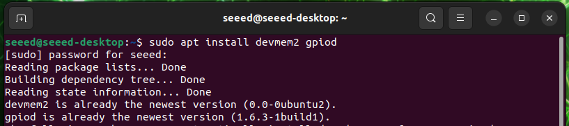
Suppose you have a working J401 carrier board with an Orin NX/Nano module, flashed the latest JetPack 6.x. Once you power the device, please install the following packages:
sudo apt-get update
sudo apt-get install devmem2 gpiod
Check your current I/O configurations
sudo /opt/nvidia/jetson-io/jetson-io.py
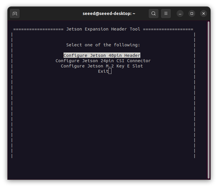
Select Configure Jetson 40pin Header
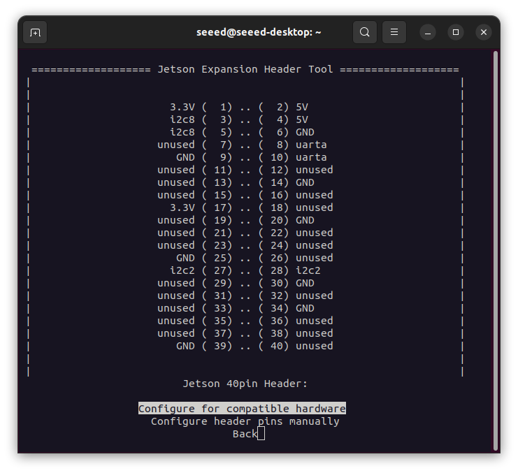
From the display above, you may know which pins are used for special purpose and which pins are unused.
Enable GPIO Pin for Output
Hardware Connections
Select which unused pin in 40 Pin Header you wish to use. In this example we’ll use Pin 31 in 40 Pin Header to light up a LED module.
Tools to prepare:
- DuPont wires
- Grove LED
- Grove to Male Cable
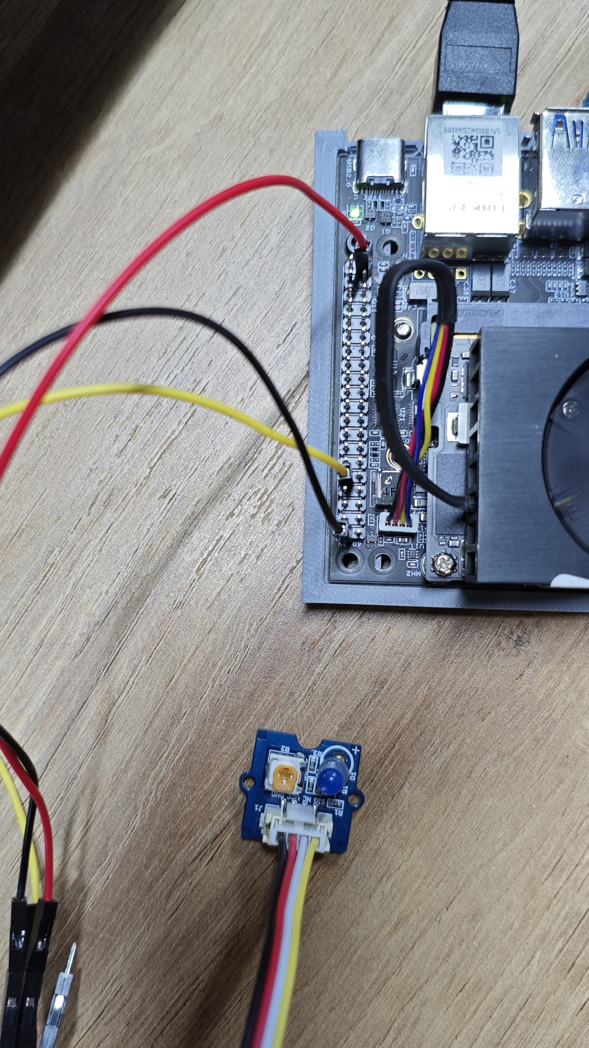
Connect the module as following:
| Grove Connector Pin Name | J401 40 Pin Header |
|---|---|
| 5V | Pin 2 |
| GND | Pin 39 |
| NC | No connect |
| SIG | Pin 31 |
The LED module takes the digital input of SIG, when SIG is HIGH, BLUE LED will light up, otherwise it stays off. We’ll set Pin 31 on board to output mode and write values to LED module.
After connecting the hardware, we need to enable our Pin 31 on bard, which is also called GPIO11 in Jetson SODIMM Signal Name and GPIO3_PQ.06/unused_SOC_GPIO33 in customer usage. We need the later one (You can find them in Pinmux Spreadsheet), refer to Changing PinMux
- Get the Pinmux register address:
-
In TRM, click System Components → Multi-Purpose I/O Pins and Pin Multiplexing (PinMux) → Pinmux Registers.
-
Search for pin name
SOC_GPIO33 -
Get complete pin name. In our case, it’s
PADCTL_G3_SOC_GPIO33_0, with offset0x70. -
Go to TRM, and in Table 1-15: Pad Control Grouping, find the
G3pad control block =PADCTL_A0entry. -
On the Memory Architecture page, click Memory Mapped I/O → Address Map.
-
Search for
PADCTL_A0, The base address is PADCTL_A0 = 0x02430000, and the pinmux register address is
-
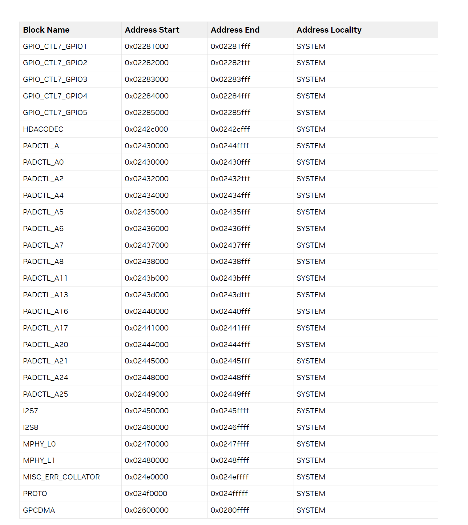
PADCTL base address + offset.
And we get our Pinmux register address = 0x02430000 + 0X70 = 0x02430070
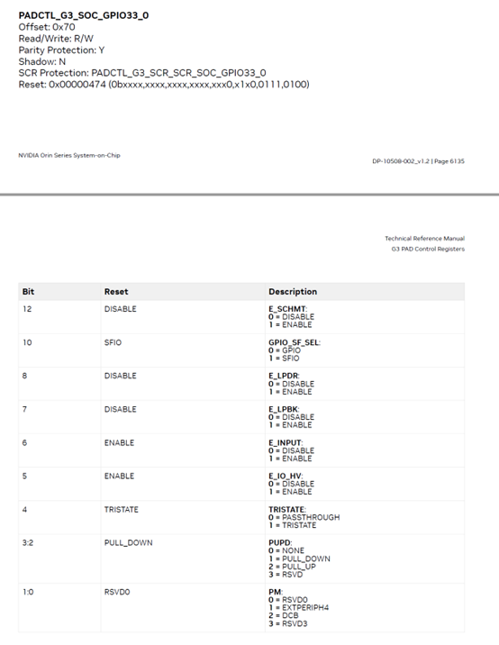
- Get current register value with
devmem2, and write value0x400to enable this pin for GPIO output mode.
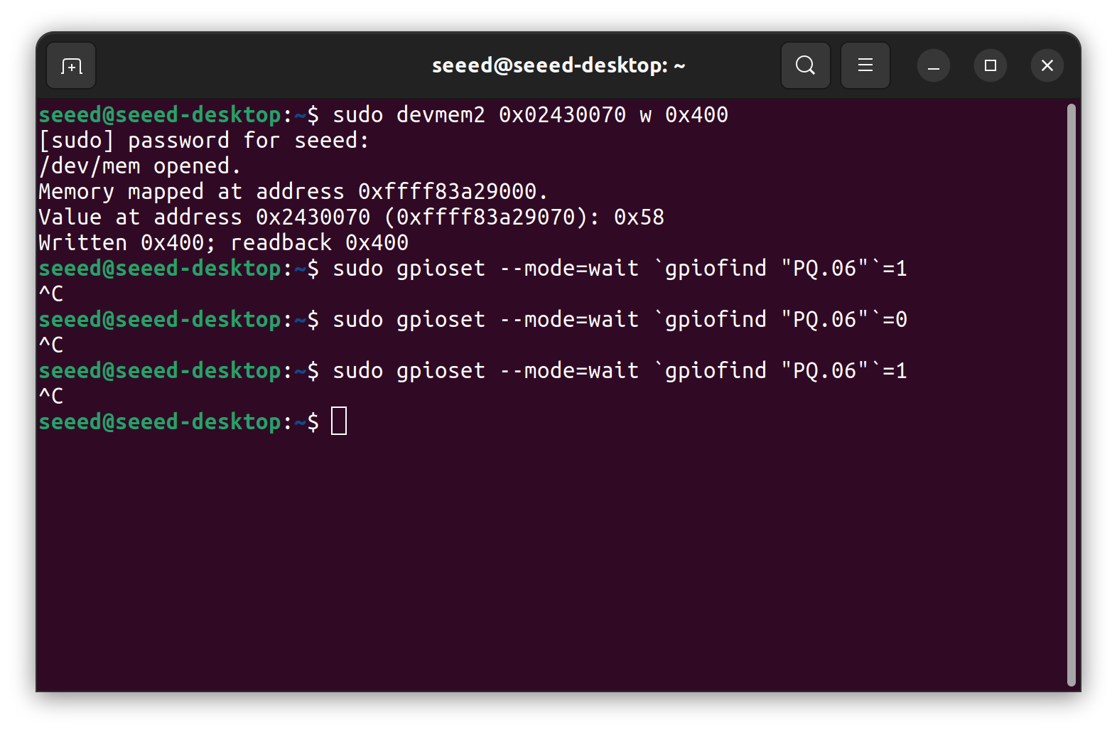
# Check current value
sudo devmem2 0x02430070

# Write value
sudo devmem2 0x02430070 w 0x400
- Using
gpiosetto write test it:
Set it to LOW
sudo gpioset --mode=wait `gpiofind "PQ.06"`=0
Set it to HIGH
sudo gpioset --mode=wait `gpiofind "PQ.06"`=1
Note that in gpioset command, usually you need use gpiofind to get the corresponding number in gpiod.
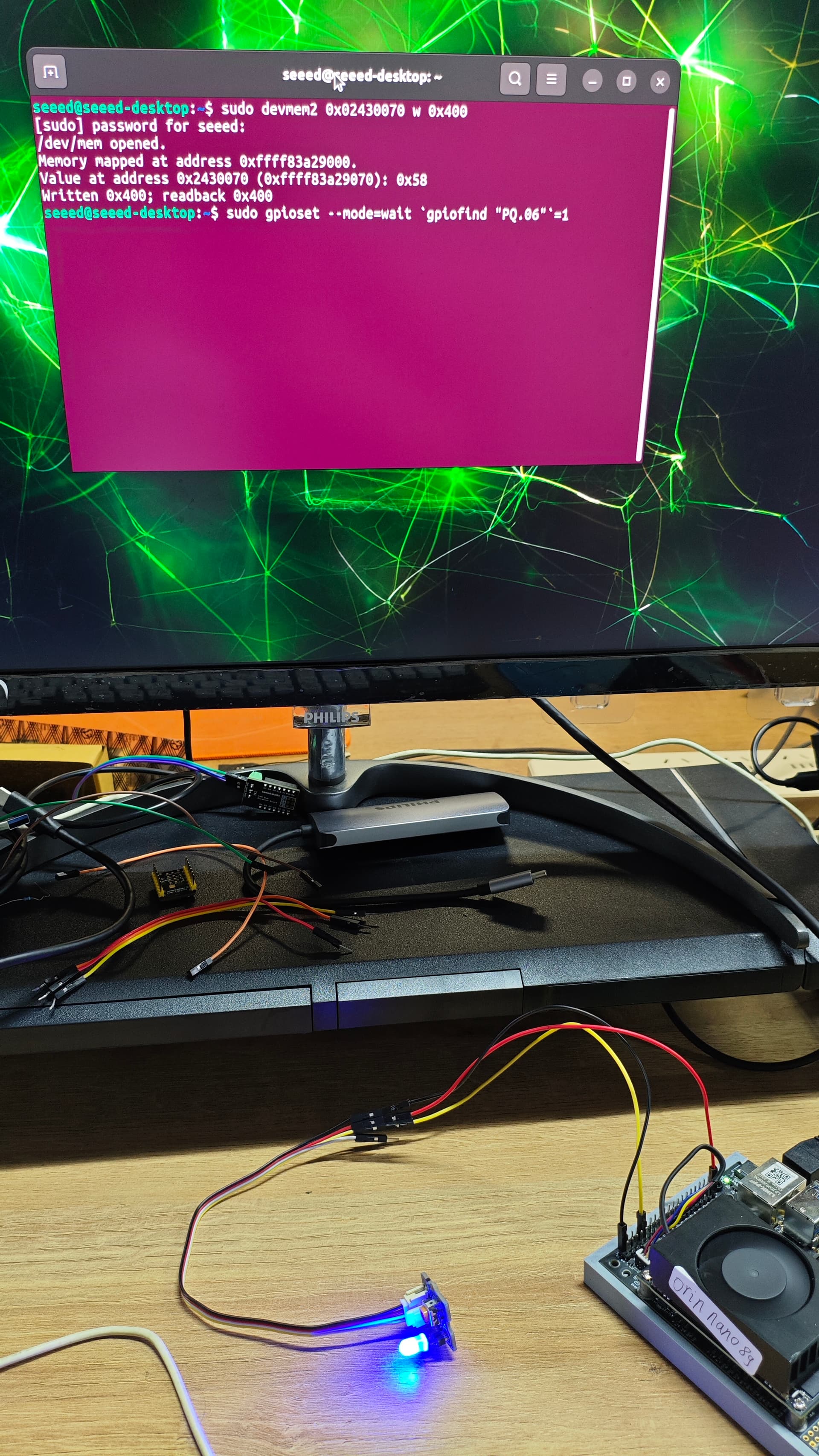
If everything went well, you should be able to see your LED light up:
Enable GPIO for Input
Alternative, according to the register operation table and the description in NV’s documentation. You can write 0x450 to corresponding register to set your GPIO pin for input mode.
sudo devmem2 0x02430070 w 0x450
We use a shell script to monitor GPIO’s reading using gpioset. This time we use a MCU to write HIGH/LOW to Jetson device, let’s see if it can read values properly.
Hardware Connection
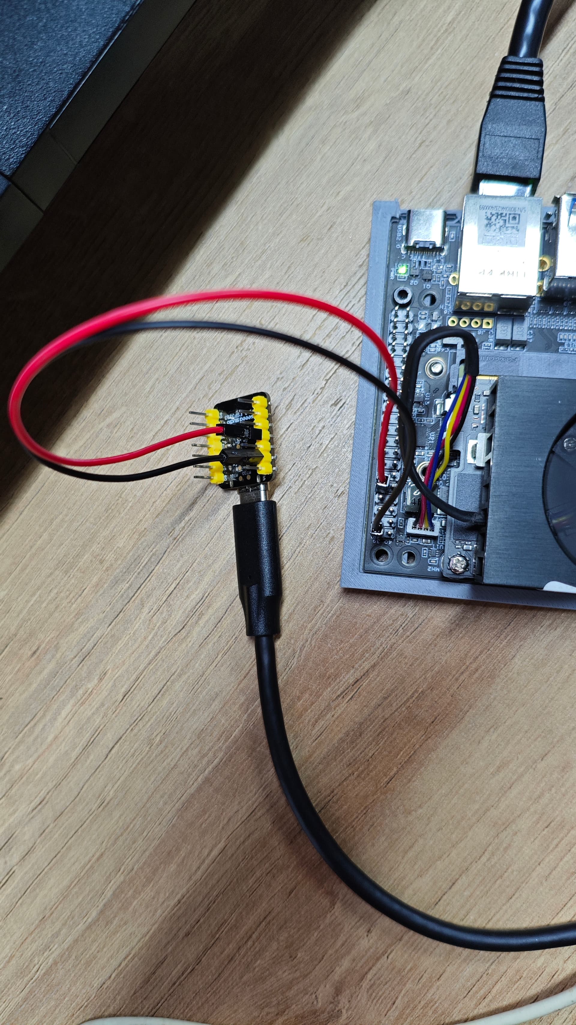
We use a XIAO ESP32S3 D10 pin to write HIGH/LOW values.
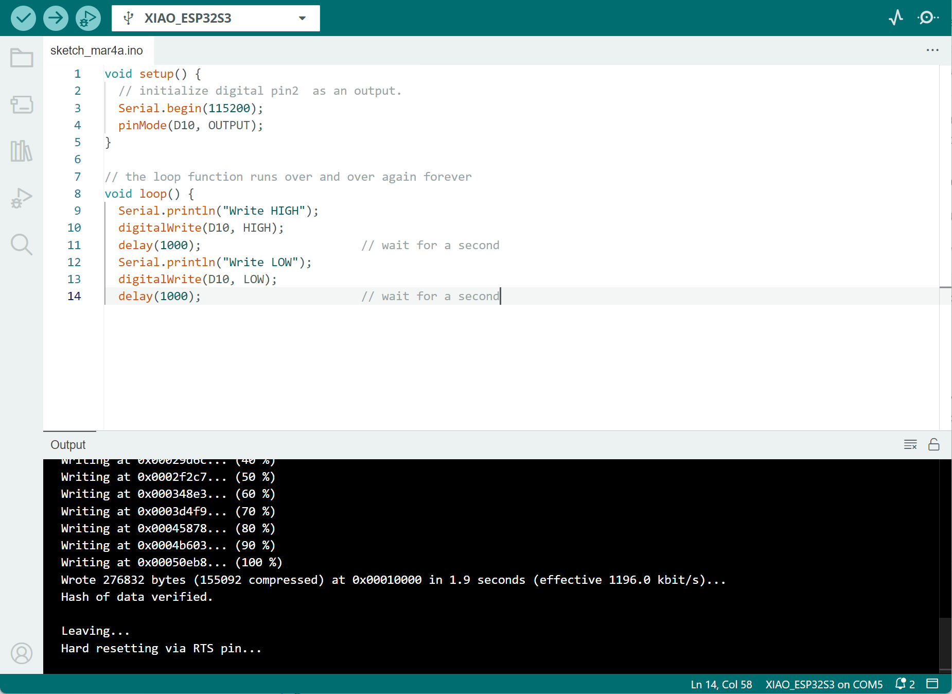
And we upload the following sketch:
void setup() {
  // initialize digital pin2  as an output.
  Serial.begin(115200);
  pinMode(D10, OUTPUT);
}

// the loop function runs over and over again forever
void loop() {
  Serial.println("Write HIGH");
  digitalWrite(D10, HIGH);
  delay(1000);                       // wait for a second
  Serial.println("Write LOW");
  digitalWrite(D10, LOW);
  delay(1000);                       // wait for a second
}
In jetson, we create the following script to monitor the GPIO value:
#!/bin/bash

# get gpio line information
gpio_info=$(gpiofind "PQ.06")

# check if gpio can be found
if [ -z "$gpio_info" ]; then
    echo "GPIO PQ.06 not found"
    exit 1
fi

# extract gpio chip info and offset
gpiochip=$(echo "$gpio_info" | cut -d ' ' -f 1)
offset=$(echo "$gpio_info" | cut -d ' ' -f 2)

# ctrl + c to terminate
trap "echo 'Terminating...'; exit 0" SIGINT

echo "Monitoring GPIO PQ.06 ($gpiochip $offset)... Press Ctrl+C to exit."

# enter the loop, read gpio value every second
while true; do
    value=$(gpioget "$gpiochip" "$offset")
    echo "$(date '+%Y-%m-%d %H:%M:%S') - GPIO PQ.06 value: $value"
    sleep 1
done
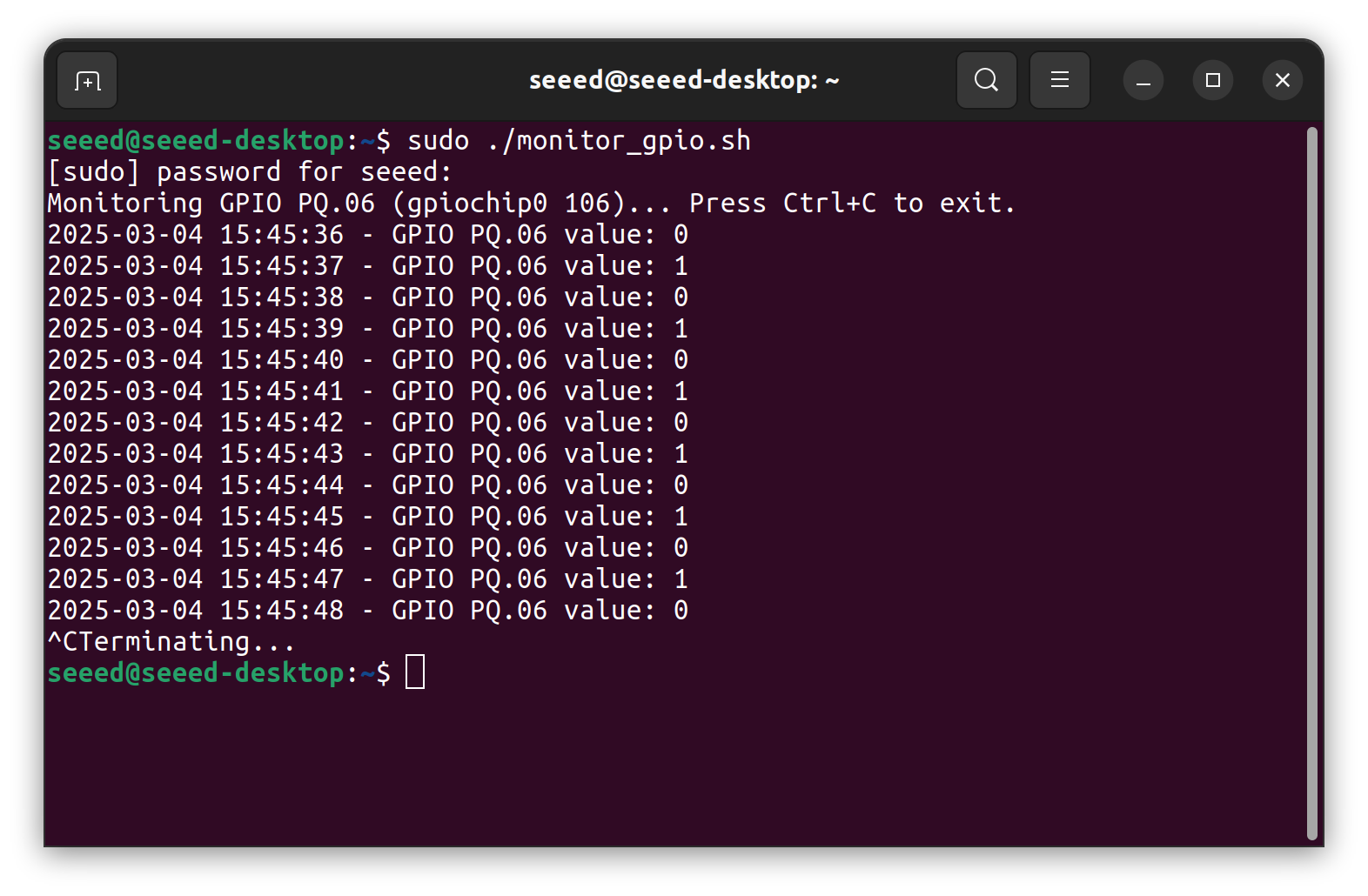
Save it as monitor_gpio.sh, grant the execute permission:
chmod +x ./monitor_gpio.sh
Execute the script:
sudo ./monitor_gpio.sh
You can see the monitor result:
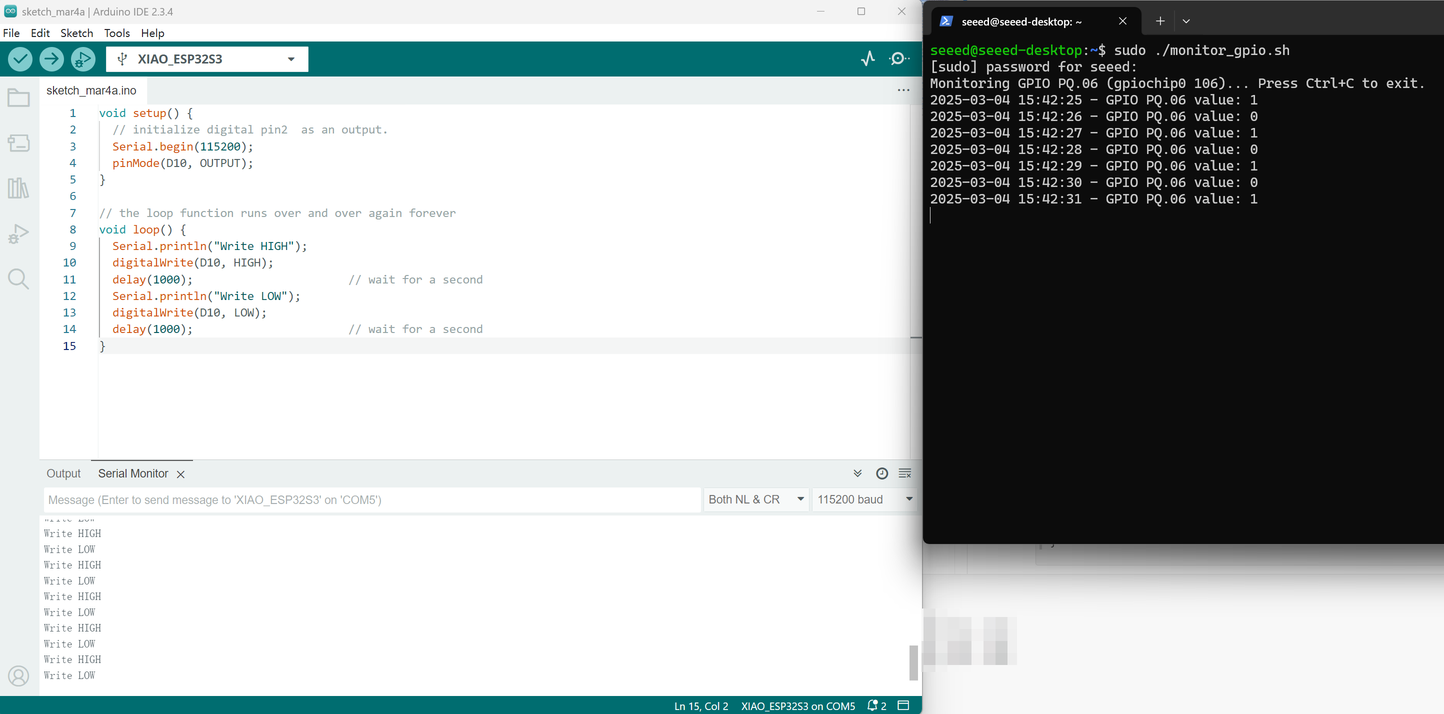
For easy reference, we put Arduino’s serial port output with the Jetson’s gpioget result in the same screen:
40-Pin Expansion Header GPIO Usage Considerations
The same is for Orin Nano and Orin NX, they share the similar design with Jetson Nano’s 40 Pin Header.