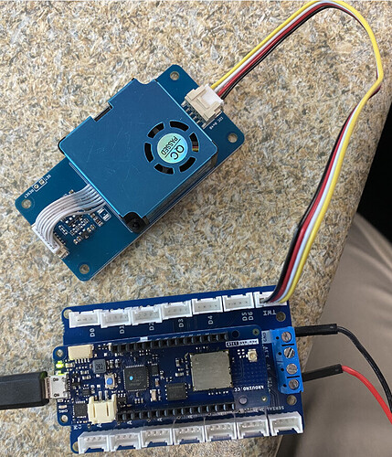
In my air quality monitor project, using the Grove Laser PM2.5 Sensor module (HM3301 , PN 101020613).
</s>11:32:07.771 -> 80  FF  BF  DF  EF
11:32:07.771 -> F7  FB  FD  FE  FF
11:32:07.771 -> FF  FF  FF  FF  FF
11:32:07.771 -> FF  FF  FF  FF  FF
11:32:07.771 -> FF  FF  FF  FF  FF
11:32:07.771 -> FF  FF
11:32:07.771 -> wrong checksum !
11:32:07.771 ->
11:32:07.771 ->
11:32:07.771 -> sensor num: 65471
11:32:07.771 -> PM1.0 concentration(CF=1,Standard particulate matter,unit:ug/m3): 57327
11:32:07.805 -> PM2.5 concentration(CF=1,Standard particulate matter,unit:ug/m3): 63483
11:32:07.805 -> PM10 concentration(CF=1,Standard particulate matter,unit:ug/m3): 65022
11:32:07.805 -> PM1.0 concentration(Atmospheric environment,unit:ug/m3): 65535
11:32:07.805 -> PM2.5 concentration(Atmospheric environment,unit:ug/m3): 65535
11:32:07.805 -> PM10 concentration(Atmospheric environment,unit:ug/m3): 65535
11:32:07.805 -><e>
Hansen
December 17, 2019, 1:42am
2
Hi There http://wiki.seeedstudio.com/Arduino_Sof … ser_guide/”>http://wiki.seeedstudio.com/Arduino_Software_I2C_user_guide/ </LINK_TEXT>.
To clarify I’m using one sensor connected to the I2C bus, the Grove Laser PM2.5 Sensor module (HM3301 , PN 101020613).
one more comment, I am connected directly to the Grove connector with 3.3V and I2C levels at 3.3V (without a grove breakout board).http://wiki.seeedstudio.com/Grove-Laser … or-HM3301/”>http://wiki.seeedstudio.com/Grove-Laser_PM2.5_Sensor-HM3301/ </LINK_TEXT>#7 of the sensor data sheet it say:
Hansen
December 18, 2019, 1:34am
5
Hi there
I’m getting the same issue, here is the output from the sketch.
4D  0  1C  0  A
0  E  0  10  0
A  0  E  0  10
A  4A  2  E6  0
7A  0  B  0  2
0  0  wrong checkSum!!!!

sensor num: 28
PM1.0 concentration(CF=1,Standard particulate matter,unit:ug/m3): 10
PM2.5 concentration(CF=1,Standard particulate matter,unit:ug/m3): 14
PM10 concentration(CF=1,Standard particulate matter,unit:ug/m3): 16
PM1.0 concentration(Atmospheric environment,unit:ug/m3): 10
PM2.5 concentration(Atmospheric environment,unit:ug/m3): 14
PM10 concentration(Atmospheric environment,unit:ug/m3): 16
I am also getting this same error - wrong Checksum! !!!
I have Arduino MKR WAN 1310 connect to Arduino MKR Connector carrier (Grove compatible). The PM2.5 sensor is connected to the TWI connector diretly. There is only one I2C device (the PM2.5 is the only connected device.
45
sensor num: 28
Also all the measured values always show as ‘1’.
The wrong checksum error is intermitant. However when the checksum is correct the sensor always reads a value of 1 for all of the measurements.
Baozhu
October 27, 2020, 12:24am
8
Does this happen often? Have you tested it on other platforms?I found no such problem in my tests .
Hi:
The Arduino MKR 1310 is my target platform for my project. I have found that if I expose the PM2.5 to dirtier environment I do get readings other than 1.
As for the bad checksum, happens most of the time. When there is a checksum error data[28] is always 0.
I cannot explain this unless somehow the data is out of synch - data[] is getting data from previous measurement and next measurement.
rsnape
September 27, 2021, 3:07pm
10
I’m getting this behaviour too. Bad checksum. I’m using i2c at 20,000 Hz, readings look plausible but the checksum is always wrong. Are there any things I could do to work out what is going wrong?
 .
.