Hi @jiachenglu,
Thanks for your response. I have listed my environment, what is objective also attached the pics of circuit.
Objective:
To measure the Voltage, Current and watts of a lightbulb/hair dryer/ any appliance.
For that I am using Grove 10 DC current sensor to measure the current usage.
I have tried the sample program (which is given by Grove team) to make sure my board and current sensor are working fine as well as to calibrator. But I am getting values in minus in randomly.
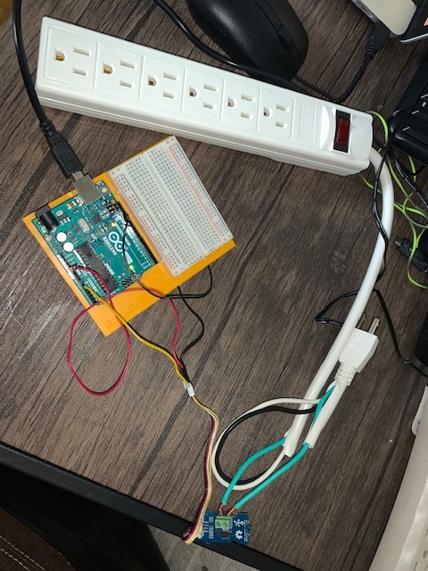
I have attached my circuit pics and Arduino program.
Environment:
Country: USA
Current type: DC current
Circuit explanation :
-
I hooked 10 A DC current sensor to my extension card ( ref image 2)
-
Serial print
21:42:34.580 → initialValue: 322.27mV
21:42:34.614 → 1.01mA
21:42:34.614 →
21:42:36.665 → initialValue: 322.27mV
21:42:36.665 → 1.01mA
21:42:36.698 →
21:42:38.713 → initialValue: 317.38mV
21:42:38.746 → -17.49mA
21:42:38.746 →
21:42:40.761 → initialValue: 317.38mV
21:42:40.795 → -17.49mA
21:42:40.795 →
21:42:42.840 → initialValue: 322.27mV
21:42:42.876 → 1.01mA
21:42:42.876 →
21:42:44.886 → initialValue: 322.27mV
21:42:44.922 → 1.01mA
21:42:44.922 →
21:42:46.964 → initialValue: 322.27mV
21:42:47.001 → 1.01mA
21:42:47.001 →
21:42:49.015 → initialValue: 317.38mV
21:42:49.052 → -17.49mA
21:42:49.052 →
21:42:51.074 → initialValue: 322.27mV
21:42:51.109 → 1.01mA
21:42:51.109 →
-
Ardunio program
Blockquote
#ifdef ARDUINO_SAMD_VARIANT_COMPLIANCE
#define RefVal 3.3
#define SERIAL SerialUSB
#else
#define RefVal 5.0
#define SERIAL Serial
#endif
//An OLED Display is required here
//use pin A0
#define Pin A0
// Take the average of 500 times
const int averageValue = 500;
long int sensorValue = 0;
float sensitivity = 1000.0 / 264.0; //1000mA per 264mV
float Vref = 322; //Vref is zero drift value, you need to change this value to the value you actually measured before using it.
void setup()
{
SERIAL.begin(9600);
}
void loop()
{
// Read the value 10 times:
for (int i = 0; i < averageValue; i++)
{
sensorValue += analogRead(Pin);
// wait 2 milliseconds before the next loop
delay(2);
}
sensorValue = sensorValue / averageValue;
// The on-board ADC is 10-bits
// Different power supply will lead to different reference sources
// example: 2^10 = 1024 → 5V / 1024 ~= 4.88mV
// unitValue= 5.0 / 1024.01000 ;
float unitValue= RefVal / 1024.01000 ;
float voltage = unitValue * sensorValue;
//When no load,Vref=initialValue
SERIAL.print("initialValue: ");
SERIAL.print(voltage);
SERIAL.println(“mV”);
// Calculate the corresponding current
float current = (voltage - Vref) * sensitivity;
// Print display voltage (mV)
// This voltage is the pin voltage corresponding to the current
/*
voltage = unitValue * sensorValue-Vref;
SERIAL.print(voltage);
SERIAL.println(“mV”);
*/
// Print display current (mA)
SERIAL.print(current);
SERIAL.println(“mA”);
SERIAL.print(“\n”);
// Reset the sensorValue for the next reading
sensorValue = 0;
// Read it once per second
delay(1000);
}[quote=“gopinathyadavstudies, post:1, topic:252227, full:true”]
Thanks in Advance
Gopinath Yadav A R
Deer Community, I hope you can help me out.
I am very new to Electrical domain. I have bought new Grove - 10A DC Current Sensor (ACS725) to measure the DC current and watts usage. so I have tried to run the sample program which is given by Grove team in link Grove - 10A DC Current Sensor (ACS725) | Seeed Studio Wiki
but I am getting -4.62mV -17.49mA values.
Thanks in Advance
Gopinath Yadav A R