I’ve just received a new DSO Quad and I’m not sure if the unit is faulty or I am!
I attached a probe to the wave out and set it to 10KHz as it said in the instructions (looks like the unit has already been calibrated). On channel B the waveform is rock solid but when using channel A the waveform is still a square wave but it’s flying around all over the place! I’ve tried both probes and done the calibration spreadsheet thing but it doesn’t make any difference.
Could the unit be faulty or is it me?
Thanks in advance for any help!
What is your trigger source, type and level?
I’m a bit new to the whole oscilloscope thing so I’m not exactly sure what answers you’re after.
Basically I connected one set of probes to the DSO’s wave out and the other to channel A. So the DSO is just generating a 10KHz square wave and then reading itself. It looks fine on channel B but not on A.
Does that answer any of your questions?
Some screenshots if it helps!
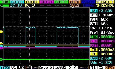
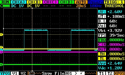
CH-A1.BMP and CH-A2.BMP are the kind of thing that channel A is flicking between.
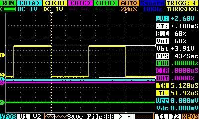
CH-B.BMP is the same reading but done using channel B.
The configuration of the unit was the same for both readings.
Bingo.
At the top right corner you see TRIG in yellow, the fancy little “falling edge” symbol and THRESHOL. When measuring on channel A, set TRIG to channel A (trigger config in the same cyan as A). The yellow line that goes horizontally across the screen and is labeled T will also change color. Place that line with the left wheel onto the THRESHOLd for the trigger event. That is somewhere in the middle between the signal’s min and max. Select the trigger event. For square signals that is usually raising or falling edge. Finally there is a vertical orange line probably hidden under the white T1 line, controlled with XPOS (orange bottom right). That controls where the scope tries to put the trigger event.
The scope needs to have a trigger event that defines how to line up the samples on the X axis. That orange XPOS defines where on the screen to put the sample, at which the event happened. In the case of your CH-B image, we see that the trigger config is “falling edge of CH-B (yellow)” and that the trigger threshold (T-line) is about 3/4 up the signal. Falling edge means that the measured voltage went from above the threshold to below it. And that is exactly what it is doing.
In the CH-A1 and CH-A2 images, the scope is configured for the same CH-B trigger event. But since B doesn’t get a signal, the event never happens and the scope displays the samples wherever they happen.
Does that make sense?
Thank you for that, It does make sense and it works!
I didn’t realise that the trigger was set on a ‘per channel’ basis. This interface could take a bit of getting used to!
Thanks again!
You’re welcome.
To be clear on this, only one channel can be the trigger source. All the samples of all channels are displayed relative to that trigger.
If you are looking at multiple signals that have the same frequency (or harmonics), then all the signals will be “steady”. But you would be able to see their relative timing. For example, if you build a standard 555 timer astable oscillator like this

connect the probes of CH-A to pin 2, CH-B to pin 3 of the 555, it doesn’t really matter which channel is used for the trigger. The two signals are in sync anyways. What you will see on your oscilloscope are the charge/discharge curve of the capacitor C and how the 555 reacts to it on its output.
On the other hand if you are measuring signals with “slightly” different frequencies, like two similar oscillators, you will see the one that is the trigger source being steady and the other one moving or jumping around.
And you are absolutely right. The interface is something to get used to.
Ok. I built that circuit and connected the DSC as you suggested, this is starting to make sense now, thanks!