Grove Connector and Cable
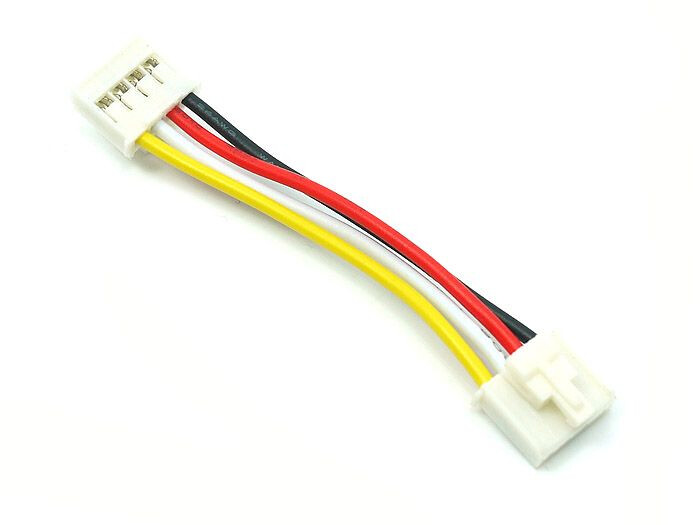
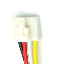
So for naming convention, according to this diagram, the connector will be oriented so the Black is to the left with the wires exiting to the bottom…. The clip connector (if equipped) will be on the top face this also matches the readable direction on the silk screen
The colors will be Black-Red-White-Yellow
The Pins will be GND-VCC-Data W-Data Y
(note: in some configurations the term Data and Signal may be interchangable, Data implying a Digital and Signal implying Analog)
(note: on some units and sensors the RED=Power=VCC may be 3v3 or 5v)

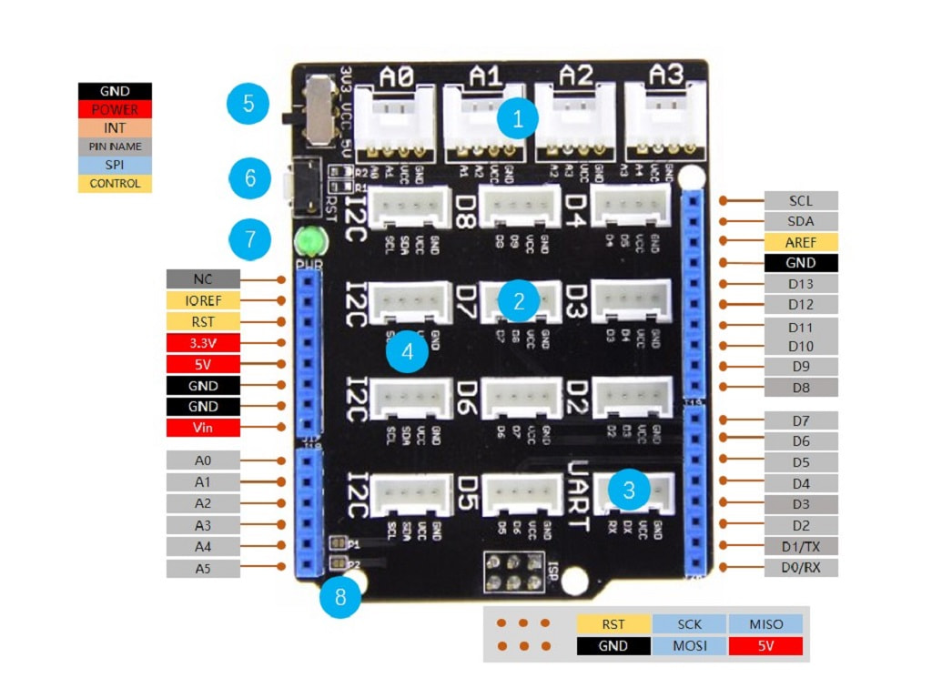
So for naming convention, according to this diagram, seeed standard is to name the port by the number of the data pin in the right most position in the grove connector, (Yellow Wire)
for example
the top row of grove ports are 0-1-2-5
the bottom row of grove ports are 5-7-8-9
as you can see… ports 5 are identical because they are an IIC bus
The unique of the IIC Bus is that multiple devices can communicate on this bus structure, as opposed to UART and others that are one port to one device configuration
(note: it is possable to only have three wires, and the Data-W position will be NC=Not Connected)
as in the D0 port on the XIAO Expansion Board

Typically the (white pin #) is = (yellow pin #+1), But this is not always true as UART and IIC are backwards
I call the data pins Data-A and Data-B where A is the lower of the 2 numbers and B is the Higher of the 2 numbers
so for example.. at Grove Port 0, the Pins will be GND-3v3-Data B(1-White) and Data A(0-Yellow)
BUT for Grove Port 5 (IIC), the Pins will be GND-3v3-Data A(4-White) and Data B(5-Yellow)
AND for Grove Port 7 (UART), the Pins will be GND-3v3-Data A(6-White) and Data B(7-Yellow)
As you can see… the Grove Connector Technology is a beautiful and ellegant solution to pin multiplexing with a standard 4 wire communication structure