Hi all, hope someone can shed a light…
My project is running on an XIAO ESP32C3 and aims to control a servo whilst also providing a 10khz PWM output for driving a motor. Whilst I can provide either of these separately, when I combine them in the same sketch, the servo output is running far too fast. I have been going around in circles trying many different methods of providing the pwm output, but am getting nowhere. Even a long session with the Gemini AI hasn’t helped.
The issue is compounded by the apparently unreliable later versions of the arduino ESP32 boards…
My test code is shown below (or one of them!)
Arduino IDE v1.8.5
Esp board 2.0.13
#include <ESP32Servo.h>

const int FetPin = 3 ; //GPIO3
const int freq = 10000;
const int resolution = 8;

const int servoPin = 7; //
Servo myservo; // for driving an ESC

int currentMotorPower=0;

void setup() {
myservo.setPeriodHertz(50); // standard 50 hz servo
myservo.attach(servoPin, 900, 2100); // min/max

// FOR DIRECT FET DRIVE 0-100% PWM Setup timer and attach timer to a led pin
ledcAttachChannel(FetPin, freq, resolution, 1); // select channel 1
}

void loop{
for (currentMotorPower = 0; currentMotorPower <= 100; currentMotorPower += 5) {
setMotorPower();
delay(100);
}

for (currentMotorPower = 100; currentMotorPower >= 0; currentMotorPower += -5) {
setMotorPower();
delay(100);
}
}

void setMotorPower() { // NB this is using both servo/esc, and a fet driver
int p= map (currentMotorPower,0,100,0,180);
myservo.write(p); // for servo version, driving an esc
// now do the pwm output
p= map (currentMotorPower,0,100,0,255);
ledcWrite(FetPin, p);
}
interesting question!.. have you tried with other XIAO ESP32’s
It looks to me like the problem is somehow in the myservo library and how it handles interupts and timing…
Hi there,
So the Servo stuff is gaining some traction, the Xiao Servo board looks pretty good too.
On the C3 you need to seperate the timers…
PWM channel conflict issue, and it’s exactly why the servo “runs too fast” when combined with a high-frequency PWM output.
The ESP32C3 has only 4 LEDC PWM timers (0–3) and 6 channels. All channels share timers unless explicitly separated. If two PWM outputs use the same timer, they must use the same frequency and resolution.
it’s an Espressif GotCha… and they did  Nrf does it better IMO.
your servo starts running at 10kHz PWM instead of 50 Hz — and goes nuts. the trick is to assign different LEDC timers to each output:
- Let Servo use timer 0
- Let your 10kHz motor PWM use timer 1
This way they don’t interfere.
#include <ESP32Servo.h>

const int FetPin = 3;     // GPIO3 for motor PWM
const int servoPin = 7;   // GPIO7 for servo
const int freq = 10000;   // 10kHz PWM
const int resolution = 8; // 8-bit PWM

Servo myservo;
int currentMotorPower = 0;

void setup() {
  Serial.begin(115200);

  // Setup servo on its own timer (LEDC timer 0 by default)
  myservo.setPeriodHertz(50); // standard 50 Hz servo
  myservo.attach(servoPin, 900, 2100); // min/max pulse width in µs

  // Setup 10kHz PWM on a different timer (timer 1)
  ledcSetup(1, freq, resolution);       // Channel 1, 10kHz, 8-bit
  ledcAttachPin(FetPin, 1);             // Attach channel 1 to GPIO3
}

void loop() {
  for (currentMotorPower = 0; currentMotorPower <= 100; currentMotorPower += 5) {
    setMotorPower();
    delay(100);
  }

  for (currentMotorPower = 100; currentMotorPower >= 0; currentMotorPower -= 5) {
    setMotorPower();
    delay(100);
  }
}

void setMotorPower() {
  // Servo output (0–180 degrees)
  int angle = map(currentMotorPower, 0, 100, 0, 180);
  myservo.write(angle);

  // PWM output (0–255)
  int pwmVal = map(currentMotorPower, 0, 100, 0, 255);
  ledcWrite(1, pwmVal);  // Channel 1
}
HTH
GL  PJ
PJ 
Thats what I thought it was…
Thank you once again for the informative help, I’ve been dancing around this one for some time - have tried assigning timer channels but never got it quite right. Unfortunately, this example give an error:
‘ledcSetup’ was not declared in this scope
I think that this is something to do with the arduino esp board definition - I’m using 2.0.13 - it’s a mystery - thanks again.
Hi there,
SO , do you know how to change (update) the BSP?
You have a boards TAB? , in the IDE ? open that and search in the box for ESP32, You’ll see this
Use the pulldown and pick the latest one. AFAIK , none of the servo LIB stuff was compatible prior to 2.1.14 to the seeed hardware. YMMV
You’ll get it you’re close…
HTH
GL PJ
You see by the shear number of posts it was a treasure hunt… the seeedineers finally stepped in and pushed a new(updated) LIB

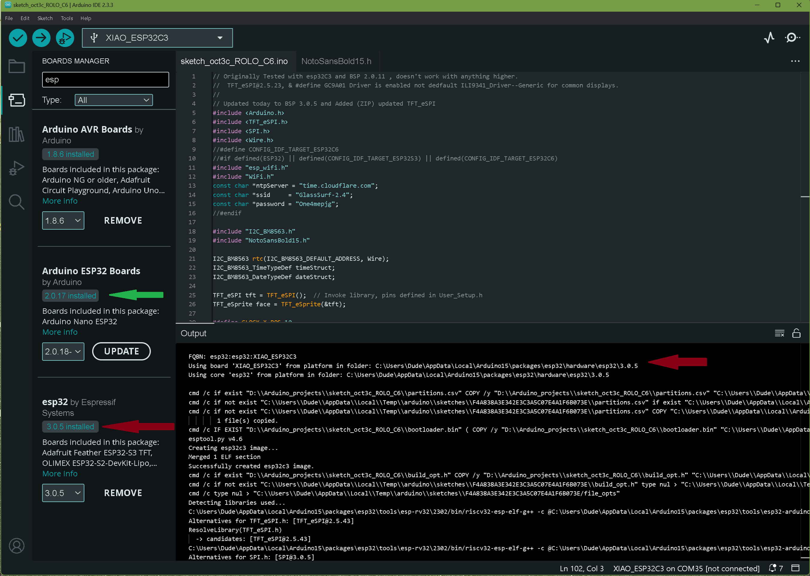
Thanks again - I had ESP32 by Expressif 3.0.7 installed, and so down graded to 3.0.5 as per your illustration. I have board 2.0.13 but this is the latest version that I can install via the IDE. I have downloaded a zip file with 2.0.17 - but haven’t figured out how to install this - it’s a shame that the IDE does not have an ‘install from zip’ option, as for libraries - will carry on, thanks.
So, I installed Arduino IDE v2 , along with the boards and libraries - but I still get the same error…meh…it would appear that the ledc methods have been deprecated.
OK - I think I have it now…
I took the examples for multiple servos and pwm from the ESP32Servo library and cobbled together the below code. At first, it did not work - until I attached the pwm pin before attaching the servo - now it works. Thanks again for the help…
 /* modified from the examples in the
  * ESP32 Servo Library
  */

 #include <ESP32Servo.h>
#include <ESP32PWM.h>


 // create  servo object
 Servo servo1;

 // Published values for SG90 servos; adjust if needed
 int minUs = 1000;
 int maxUs = 2000;

 // These are all GPIO pins on the ESP32
 // Recommended pins include 2,4,12-19,21-23,25-27,32-33
 int servo1Pin = 7;
 int LedPin=21;

 int pos = 0;      // position in degrees
 ESP32PWM pwm;

 void setup() {
     // Allow allocation of all timers
     ESP32PWM::allocateTimer(0);
     ESP32PWM::allocateTimer(1);
     ESP32PWM::allocateTimer(2);
     ESP32PWM::allocateTimer(3);
     Serial.begin(115200);
     servo1.setPeriodHertz(50);      // Standard 50hz servo

 pwm.attachPin(LedPin, 10000);//10khz  // important to do this before the servo attach!!!!
  servo1.attach(servo1Pin, minUs, maxUs);
 }

 void loop() {

     for (pos = 0; pos <= 180; pos += 1) { // sweep from 0 degrees to 180 degrees
         // in steps of 1 degree
         servo1.write(pos);
         delay(1);             // waits 20ms for the servo to reach the position
     }
     for (pos = 180; pos >= 0; pos -= 1) { // sweep from 180 degrees to 0 degrees
         servo1.write(pos);
         delay(1);
     }


// fade the LED on thisPin from off to brightest:
	for (float brightness = 0; brightness <= 0.5; brightness += 0.001) {
		// Write a unit vector value from 0.0 to 1.0
		pwm.writeScaled(brightness);
		delay(2);
	}

	for (float brightness = 0.5; brightness >= 0; brightness -= 0.001) {
        	pwm.writeScaled(brightness);
		delay(2);
	}


     delay(1000);

 }
Hi there,
Great Job , Staying with it…
GL PJ
Unfortunately, I spoke too soon…having put the 'scope on the PWM output, it is running at 50hz, same as the servo - I need 10khz. The hunt continues.
@David_Lane I’m not sure if you’re having the exact same problem as I, but I found that when I was trying to use two different frequencies for LedC on ESP32, I had to “throw away” a channel between.
here’s what I have:
#define LEDC_TIMER_BIT 12
#define LEDC_TIMER_BIT_MAX ((1 << LEDC_TIMER_BIT) - 1)
#define LEDC_TIMER_SHORT_BIT 20
#define LEDC_TIMER_SHORT_BIT_MAX ((1 << LEDC_TIMER_SHORT_BIT) - 1)
...
const int one_fifty_hertz = 150;
const int ten_hertz = 10;
ledcAttach(PWM_WRITE__PUMP_CONTROL, one_fifty_hertz, LEDC_TIMER_BIT); // 150 Hz
ledcAttach(THROW_AWAY_PWM_PIN_1, one_fifty_hertz, LEDC_TIMER_BIT); // HACK: Throw away this ledc channel, so that subsequent channels work?

ledcAttach(PWM_WRITE__HARNESS_FEEDBACK, ten_hertz, LEDC_TIMER_BIT); // 10 Hz
ledcAttach(THROW_AWAY_PWM_PIN_2, ten_hertz, LEDC_TIMER_BIT); // HACK: Throw away this ledc channel, so that subsequent channels work?
ok, many thanks for that. I must have tried so many combinations of ‘virtual’ channels… but when I get chance I will definitely have a go with this method, cheers