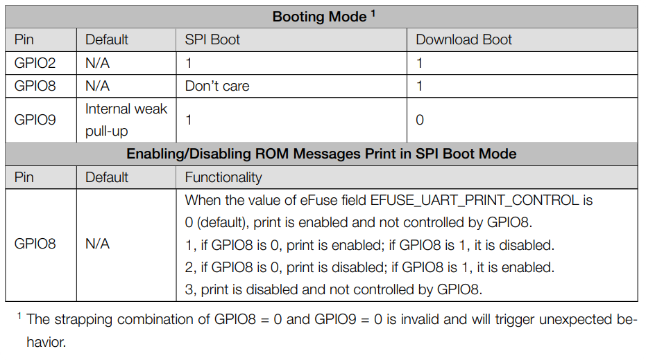
I can get my MG24 Sense into this state where it becomes unresponsive and no new sketches can be uploaded to it. I am using a buck converter and a battery, and I think there’s something with that setup that can get the XIAO into this state if a connection gets disconnected before the battery is unplugged or something, but it is hard to tell sometimes. I can’t tell if it is stuck asleep, or if it is something else. I have code on it where a button click should wake it up, but it won’t. Plugging the USBC into the computer turns the red light on, but uploading sketches results in the cannot read IDR error. Is it just bricked or could there be a way to recover it?
Hi there,
It’s a SOFT Brick… You can un do it. Check out the other thread has it in there, hold the GPIO and plug in USB… fixes it up. AOK.
Welcome to Level Two ![]()
![]()
HTH
GL ![]() PJ
PJ ![]()
@Dave_Reese - To save you hunting the “other threads” for this information…
The “GPIO” to hold low is Pin D0 on the XIAO MG24.
To clarify - it’s not really a “brick”, rather you may have put the device into a Deep Sleep - and when it “wakes”, it immediately goes back to sleep.
This prevents the device from being able to be reprogrammed.
Thanks so much guys. What does it mean to hold the gpio pin low? Sorry ![]()
bring the pin to ground… this can be done with a button or jumper
Yea, What he said ![]()
![]() @grobasoz … we have all done it.
@grobasoz … we have all done it.
Ah’ the thrill of learning, C’mon in the water is Fine ![]()
I used a paper clip once, so…no shame in that game,.
the good news is they all doit , bad news only some can be brought back… ![]()
well easily…
HTH
GL ![]() PJ
PJ ![]()
a digital pin can have 3 states… being brought low is connecting to negitive and results in a 0 value on the pin… being brought high is being connected to positive and results in a 1 … the problem is when the pin is called floating and it is neither connecte high or low and the state is not determined and may switch b etween +/- withour rhyme or reason… sometimes electrical noise will cause unexpected behavior sometime you will set a pull up or pull down resistor to ensure the base state of the digital input is in the state you expect. for example a digital push button pin may be pulled to ground by a resistor…this makes sure the state of the pin is 0… the button connects to the positive… and when it is pressed it will bring the voltage level on the pin up to 1. if you do not add this pull down (OR UP) resistor to the circuit you can have errors
I guess it is not recoverable. I connected one end of a button to D0 and the other to ground, plugged it in and tried reuploading the sketch. Still the same error
I just connect D0 to ground and press reset button. It normally works. They’re pretty hard to “break” unless you connect “big” power to the pins or 3V3 for a while…
Also make sure you have only 1 device plugged in at a time.
make sure you are pressing the button during powerup then you can release
This is for the C3 … but similar concept
I appreciate that. It still doesn’t seem to be recovering. I tried it with the button and I tried just connecting D0 to ground with at wire. Plugging it in to usb and holding the reset button doesn’t seem to be doing it either.
Very odd… I have another option if you’d like to continue trying? I’ve just “bricked” an MG24 here and tried and all worked OK.
It was mentioned by Seeed some time ago - check this post…
Basically there is a “recover” batch/script that can be run to try “recover” the device. It does help to have the D0 shorted to ground when reset or plugged in - then run the recover script.
If you get stuck - let me know.
Thanks again. I did try that erase script described in there as well to no luck. I tried it again after connecting D0 to ground - still no. ![]()
The script actually gives the same error (cannot read IDR)
That’s no good. The recovery script is quite a brute force approach.
At this stage I’m thinking you may need to look at using an external programmer to check things? It could be your XIAO’s flashing device (on board SAMD21) is not working properly. Apart from that, the XIAO may actually be toast?
You’d need to use with the expansion board (for example) or solder wires on to the underside. You’ll also need a SWD programmer.
Let me know if you want more help going this route.
I’m starting to wonder if it isn’t a soft bricked sleeping issue, but more of a EEPROM issue due to low or irregular power?
I found something that says the programming process is interrupted (e.g., due to power loss), the existing data can be corrupted, potentially rendering the chip unusable. This seems like it could be the issue.
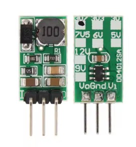
The sketch will run fine when plugged into the computer, but if you unplug it and plug in a battery (again, I am using the battery pads on the back plugged into a buck converter and then into a standard 9v - the 9v is a hard requirement for my project) My fear is something is up with this setup providing reliable power and that’s screwing something up at a crucial moment with the EEPROM and corrupting the chip.
I’ve tried to replicate this a few times now and it seems sometimes things work fine, but sometimes not. I’d say it’s twice as likely to brick as it is to work, and it’s very, very sad.
Is a step-down converter connected to the battery pads on the back instead of a battery? Nothing other than a battery can be connected to the battery pads.
Yes. It goes battery pads at the back of the chip to the buck converter and then on to the battery. Should I be using the pins on the side?
Edit: oh I guess there is also those tiny 3.3v and ground pads on the back as well. Maybe I’ll try that
Try using the USB C connection to power the XIAO MG24 when “recovering”.
If you need 9V, use a 9V → 3V3 into the 3v3 Pin (12), or a 9V->5V into the USB C or VBus(14) Pin.
If you want to (specifically) use the battery connections, use a Schottky Diode in series (Anode to PSU, Cathode to XIAO).
As an aside I use the battery pins (with diode) for power testing so I’m not sure why you’re getting errors.
Dave_Reese,
Like you, I was unable to upload to MG24. Has the problem been resolved since then?